 The purpose of How to Destroy a Spacecraft in 7 Easy Steps is to emphasize how easy it is to inadvertently make bad design and manufacturing decisions which can not only affect astronauts in the space program, but can extend to all sectors and endanger lives, products and companies. We honor the men and women who’ve given their lives to advance our space program.
Many of us know the story of how the Apollo 13 spacecraft blew her oxygen tanks near the moon, nearly costing the lives of three astronauts, but through heroic acts and ingenuity, managed to limp home with all her crew intact.
The incident nearly derailed the Apollo space program – but few of us know how it all came to pass.
Step 1: Do not verify all system component values
When Beech Aircraft, who contracted to provide the oxygen tanks to NASA, was instructed to change the voltage rating on oxygen tank electrical systems from 28 volts to 65 volts so they would be uniform with the other NASA systems, they complied, but missed a thermostat switch. This, in itself, did not cause the problem, but under the right circumstances would prove to be significant.
Step 2: Perform maintenance procedures haphazardly
When North American Aviation factory technicians were attempting to remove the shelf the oxygen tanks were stored on for servicing, they forgot to remove one of four bolts which held the shelf in place, so that when a crane lifted the shelf, it tilted the shelf up at one end, slamming it against the hydrogen tank shelf immediately above, and knocking loose the oxygen tank #2 fill tube, which could not be seen or assessed because it was inside of the tank.
Step 3: Do not provide transparency into events which could have damaged components
When other technicians at Kennedy Space Center attempted to empty oxygen tank #2 using the filler tube, it would not work. These technicians tried to understand what was wrong, but since they were not informed of the incident where the oxygen shelf was slammed into the hydrogen tank shelf, they were missing a key detail which could have alerted them to a much bigger problem with the oxygen tank. As it was, they made some wrong assumptions about why the oxygen tank would not fill, and proceeded to make further mistakes.
Step 4: Use workarounds on components that are critical to the system
Since the technicians could not empty the oxygen tank using prescribed methods (because the filler tube was loose), they had two choices; replace the tank, or they could heat and stir the oxygen to make it boil from a liquid into a gas and thus filter out through the vents. Replacing the tank was a big task which might make them miss their launch window. They ultimately decided to turn on the internal tank heater for several hours to boil off the liquid oxygen.
Step 5: Use systems that are ‘black boxes’ and whose status cannot be easily assessed
Because the tube was loose inside of oxygen tank #2, and there was no prescribed procedure to test its functionality (other than the fact that it could not be used to empty the tank), technicians were unable to make a correct diagnosis.
Step 6: Use measurement devices which peak at arbitrarily low values & fail to anticipate the unexpected or give accurate readings
As the technicians at Kennedy Space Center engaged the internal tank heater for several hours on oxygen tank #2, they noted that the thermometer showed an increase in temperature; however, since the thermostat switch was rated at only 28 volts, the 65 volt power in the system welded the thermostat switch shut, causing the heat to climb to 1000 degrees, melting the Teflon coating over the internal wiring in oxygen tank #2. The technician had a gauge to check the tank’s internal temperature, but it topped off at only 80 degrees, because under normal circumstances it would never go higher than that. Thus, the technicians heating the tank were led to believe that the heat inside the tank was only 80 degrees, instead of the actual 1000 degrees.
Step 7: Don’t test critical components just prior to launch
 When Houston instructed astronaut Jack Swigert that the oxygen tank temperature was low and needed to be heated, he flipped the heater switch, and the now-bare wires in the oxygen tank #2 caused a spark, igniting what was left of the Teflon insulation.
Pressure and temperature raised until the neck at the top of the tank failed and released oxygen into the equipment bay outside of the service module. When abundant oxygen meets flame, explosions occur, which blew open the piping shared by both oxygen tanks, blew off a side panel on the service module, and all the precious oxygen the astronauts were supposed to breathe on the journey was now lost in space.
This explosion also damaged the power unit in the service module, forcing the astronauts to move from the command module into the lunar module (which they would not be able to use to get to the moon, but would be greatly appreciated as a sort of ‘lifeboat’). The lunar module was equipped with chemical cannisters (air filters) which could scrub carbon-dioxide to make it breathable for two men over a 36-hour period, but now there were three men who would need to breathe the lunar module’s scrubbed air for 96 hours.
One would think you could just borrow some of the chemical cannisters from the command module and use them on the lunar module, but of course, the command module air filters were square, and the lunar module filters were round; no one had anticipated that astronauts might need to swap the air filters between modules.
This oversight forced technicians on the ground to work out a way for the astronauts to use spare equipment such as space suits and duct tape to adapt the command module air filters for use in the lunar module, which was so brilliantly portrayed in the movie ‘Apollo 13’.
You can see the guy who solved the air filter puzzle showing the solution in this clip: How Duct Tape Saved the Lives of the Apollo 13 Crew
This raises a question: What can we learn from Apollo 13 in regards to design and manufacturing?
How to compromise design and manufacturing CAD data in 7 easy steps
Step 1 – Rely on customer documentation or visual inspection to know what has changed in a customer revision
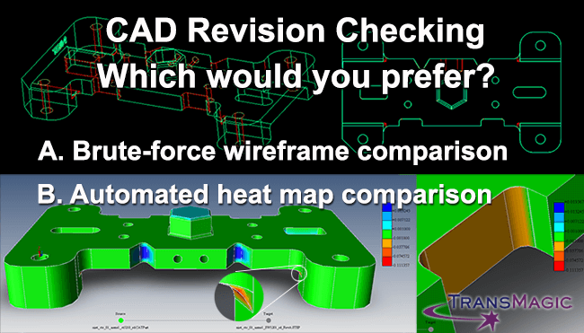
Figure 1 – Brute-force visual comparison cannot compete in terms of speed or precision with automated revision comparison which gives you graphical feedback and can generate reports.
When a customer sends you a revision and indicates that only one dimension has changed, you can take their word for it, or you can go a step further and do a visual inspection.
A visual inspection is what the Kennedy Space Center technicians attempted on oxygen tank number 2, but they could not see through the tank walls to the disconnected fill tube.
In the CAD world, a visual inspection against the current revision and the previous version is often done by overlaying both models, changing each model to a different color (red and green), and switching to wireframe display mode. This brute-force visual inspection can sometimes catch changes the customer failed to mention, if they are not too small.
Or you can go the extra mile and use specialized comparison tools which will show you exactly what changed, where it changed, and how much it changed in seconds, giving you a view into the model to see things human eyes might miss. Learn more about TransMagic MagicCheck here.
Step 2 – Do not put thought or effort into choosing the optimal CAD format for each situation – just default to STEP for all CAD translations
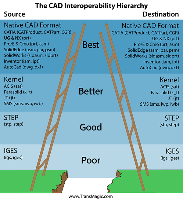
Figure 2 – There is a hierarchy to which formats contain the most information, whether you’re reading or writing CAD data. The rule of thumb is, go as high up on the CAD Format Ladder as possible.
STEP is the de-facto translation standard that surpassed IGES in the 90s and if it was good enough then, it should be good enough for now, right?
Using STEP for all translations is a little like using a temperature gauge that only goes to 80 degrees; there are a lot of assumptions being made which limit the quality of the feedback.
Actually, the format you use for different situations can have a big impact on the quality of the translation and thus the quality of the CAD data.
The CAD Format Ladder helps you choose the right format for every translation. When possible, use the native CAD format, and if you can’t use the native format, favor the geometric modeling kernel formats over STEP because they are more precisely written and will do a better job of translating the underlying geometry. Learn which CAD systems use which geometric modeling kernels here.
Step 3 – Use the translators that you have handy, or that come with your CAD system
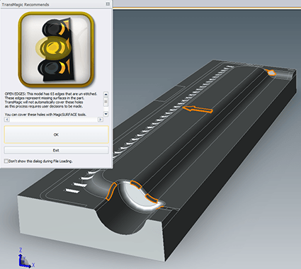
Figure 3 – Missing geometry due to poor translators creates additional work for designers and engineers.
All translators are basically the same, and they will provide you with a good STEP file, right?
Actually all translators are not created equal, and we’ve seen that repeatedly with CATIA translators and STEP translators; sometimes organic geometry is missing, and often we find that STEP translators are written to convert all geometry to splines; splines are the lowest-level, easiest way to describe complex geometry, whereas analytic geometry more accurately describes edges, planes, arcs and cylinders and is more effective in downstream applications, and NURBS support is essential to capture some of the elements generated in high-end CAD systems.
Try the evaluation version of TransMagic and see for yourself.
Step 4 – Do not validate geometry that is translated
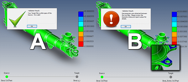
Figure 4 – Validation Analysis can instantly tell you if the geometry has changed beyond the tolerance you specify.
Geometry won’t change when you translate it, will it?
When you’re working on some aerospace projects, the customer (Boeing, for one) may ask you to validate that the file they gave you is within .005 or some other tolerance of the model you are giving them back, for exactly the same reason that NASA now pays much closer to attention to early warnings, such as an oxygen tank not emptying properly. Mistakes at 30,000 feet, or when approaching the moon, can spell disaster.
The truth is that translations sometimes change geometry and so in some cases it needs to be checked. TransMagic MagicCheck has validation capabilities and will produce a color heat map as well as a validation report. Learn more about MagicCheck and the benefits of Validation Analysis here.
Step 5 – Do not use Model Based Design (MBD) and Product and Manufacturing Information (PMI)
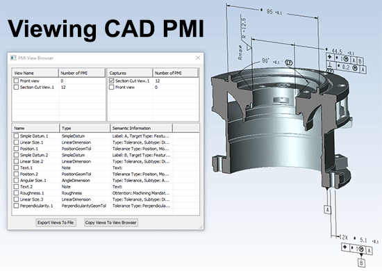
Figure 5 – MBD & PMI can give you the advantage of seeing your manufacturing details on the model for clarity and keeping all information with one source rather than risking out of sync models and drawings.
3D CAD models and 2D drawings have worked for decades, and it’s good enough now, right? Actually, Model-Based Design is gaining a lot of momentum, because having the dimensions and GD&T right there on the model makes it clear exactly what geometry the note goes to, and by having the data in one file, there is no danger of the model and drawing being out of sync if someone forgets to update one or the other.
Out of sync models and drawings is asking for trouble, because a part created to the wrong dimensions may not work at all, and could lead to wrong parts, derailed projects or even endangered lives. In the figure above, the PMI View Browser is being used to create a PMI section, saving the major auto manufacturer who requested this feature the hassle and risk of creating over 100 sections on a wall-sized drawing. Learn more about MBD and PMI here.
Step 6 – Only allow stakeholders who have access to CAD systems to see design documents
You can’t afford to give a CAD system and CAD training to every person who is a project stakeholder, right? Today, there are more options that can save your company time and money. 3D PDF and WebGL are lightweight formats that can allow anyone who can view a PDF to see the CAD model in 3D, complete with zooms, rotates, assembly structure and PMI (Product and Manufacturing Information such as GD&T, Geometric Dimensioning and Tolerancing).
For users who need more functionality, all core versions of TransMagic are simpler and less costly than full CAD seats, and can allow them to open and view any major 3D CAD format in the world, measure and interrogate the CAD geometry, and much more. Check out the TransMagic Product Wizard, an interactive tool which can help you determine which version of TransMagic you need, based on your requirements.
Step 7 – Do not automate processes such as model repair and translation
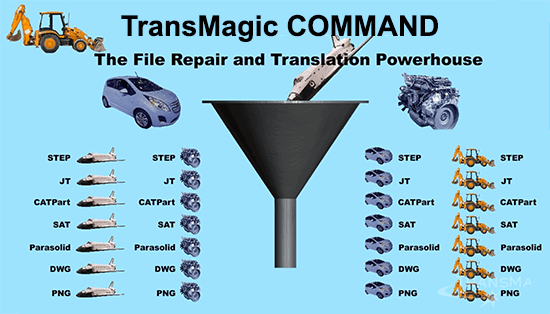
Figure 6 – Enterprise solutions like COMMAND can automatically translate all files in any given department automatically to any and all formats of your choice, so that no team member is ever waiting for their data. Other solutions, like MagicBatch, can translate thousands of files on-demand in one go.
The term Computer Aided Design itself speaks of automation; CAD systems automate the creation of lines, arcs, models, features and edits. But are we content to stop there? What if model repairs and translations could also be automated? The Apollo 13 technical teams were in a rush to get the spacecraft ready for a trip to the moon, through a window that would not open again for another month.
Most design and manufacturing firms are in a similar hurry to get designs complete and products manufactured. Automation means that many CAD model repairs can be made with a single button click in mere seconds, without pulling designers and engineers away from their primary work to make model repairs. Rather than doing translations piecemeal, translations can be batched to convert thousands of models in a few hours, and translations can even be processed instantly to multiple formats simultaneously for entire departments. Learn more about batch and enterprise translation automation here.
Three astronauts died in Apollo 1 due to an electrical fire in the cabin which burned out of control in a pure-oxygen atmosphere. Seven astronauts died on the Challenger when an O-ring seal failed due to colder than recommended launch conditions. Another seven astronauts died when the space shuttle Columbia broke up upon reentry in 2003, when a large piece of foam, which was known to be a problem, fell from the shuttle’s external tank and damaged the spacecraft wing. One thing all these incidents (including Apollo 13) had in common is that the problems were known about beforehand, but for various reasons, were not addressed properly. We can learn from these disasters; for the sake of good design and manufacturing, known problems should be dealt with as effectively as possible.
Reference: Chiles, James R., Inviting Disaster – Lessons from the Edge of Technology, Harper Business, 2001