Jan. 6, 2024
Denver, Colorado – January 6, 2024 – TransMagic, a leading developer of CAD Interoperability solutions, proudly announces the release of R14 SP1, adding several new CAD format versions as well as new time-saving features to multiple products.
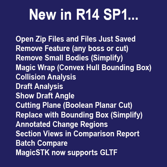
R14 SP1 picks up where R14 left off – Release 14 had an impressive 13 new features, and SP1 does that one better with 14 new features. “This release has something for everybody” states Brad Strong, product manager. “The ‘Open Zip Files’ and ‘Open File After SaveAs’ tools make the little things like finding and opening files go faster, and those small gains add up over the course of a day or week. The simplification features such as ‘Remove Feature’, ‘Remove Small Bodies’, and ‘Replace with Bounding Box’ give users who are wrestling with huge customer assemblies a way to manage file size, weight and complexity to get more work done faster.”
“At TransMagic, our mission is to get customers the files they want in the formats they need”, states TransMagic CEO Todd Reade. “We’re proud of the fact that the vast majority of these enhancements were customer-driven.”
New CAD & Polygonal Format Versions
-
CATIA V5 2023 R33
-
CATIA V6 2023 R33
-
ACIS 2023
-
NX 2212
-
Creo 9.0
-
JT 10.8
-
SOLIDWORKS 2023
-
AutoCAD 2022
-
Inventor 2024
-
Solid Edge 2024
-
Parasolid version 35
-
TMR R14
-
3D PDF up to 2023
Features Available in TransMagic R14 SP1, All Core Products
Open Zip Files (R14 SP1)
Open zipped files transparently and select the part or assembly of choice
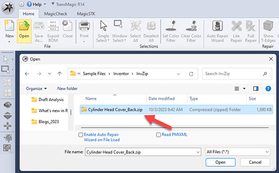 Sometimes you get a Zip file from a customer or supplier, and you have to extract the file so you can even get to it.
Now, TransMagic lets you open the zip file directly, and select the part or assembly you want to work with, saving you the unzip time and hassle of fighting through folders and files.
Open File Just Saved (R14 SP1)
Open the file you just saved automatically for quick inspection
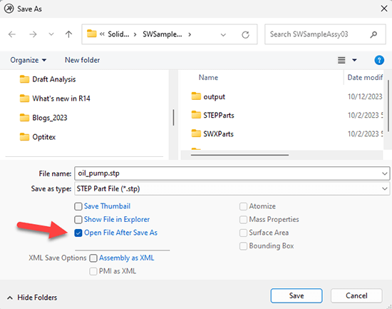 Open File After Save As will immediately open the file you just saved so you can inspect it proceeding with your design & engineering work, or before sending it on to your internal or external customers.
Conveniently located at the bottom of the Save As dialog box, this little checkbox will save you the time and hassle of locating the file you just saved, every time you use it.
Simplification Features Available in EXPERT & MagicHeal
Remove Feature (R14 SP1)
Select the key faces for any boss or cut, then click Remove Feature
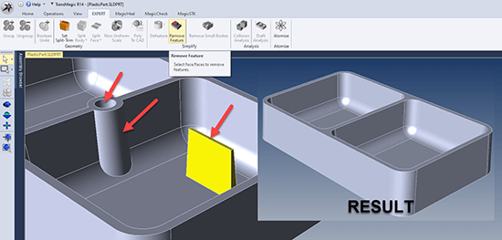 At right, all five faces of a boss are selected, using the Single Select arrow tool (on left toolbar). Then click Remove Feature from the EXPERT or MagicHeal toolbar to remove the feature.
In the screenshot at right, the boss has been removed, then the inside of the hole was selected and removed, then the post in the middle of the part.
The key to using Remove Feature is to select all the faces that define that feature, but do not select faces that tie that feature to the larger part.
Remove Small Bodies (R14 SP1)
Remove fasteners and other small or unnecessary components to lighten assemblies
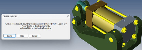 Remove Small Bodies prompts you to either Select a body to measure as a typical small body to remove, or click More, which will give you the ability to enter the X, Y and Z dimensions of the part bounding box you want TransMagic to search for.
If you use the Select option, you must first select the component you want to select, then click the Select button. In the screenshot, all parts with a bounding box volume of less than 1”x1”x1” have been selected for deletion.
Magic Wrap (R14 SP1)
Wrap a Convex Hull bounding box around selected geometry
 As with a standard bounding box, Magic Wrap covers the selected geometry but uses a convex hull bounding box for a tighter wrap around angles and curves.
The ‘Magic Wrap’ convex hull bounding box is a solid body and can thus be used for Mass Properties, Surface Area, Boolean Operations, etc.
Advanced Features available in TransMagic EXPERT
Collision Analysis (R14 SP1)
Analyze an assembly to determine which parts touch and intersect
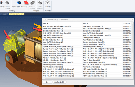 Quickly analyze if a selected part touches other components, or interferes with other components.
In the screenshot, Short Shaft has been selected in the spreadsheet (see red arrow), which causes it to turn yellow in the screen area (another red arrow), so any bodies it is touching will be shown on the spreadsheet.
In the spreadsheet, the ANSI clips are shown, as well as the Piston Rod – all bodies touch each other from outside (see orange arrows).
Draft Analysis (R14 SP1)
Draft Analysis shows you the draft of faces in the part
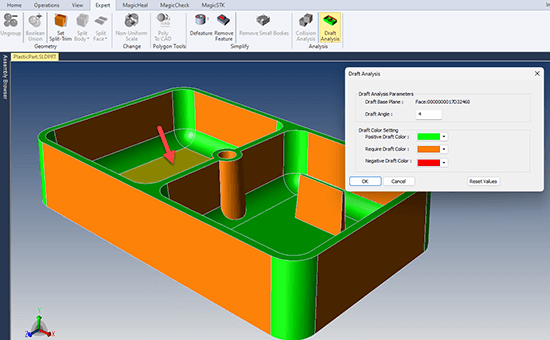 Select a face (see red arrow in screenshot) and enter a required draft angle; Draft Analysis will show you all geometry inside and outside that limit.
In this case, the Draft Angle entered is 4 degrees. Green geometry has 4 or more degrees of draft, but orange geometry does not. If we change the Draft Angle to 3, all geometry in this model will be green.
If there is an overhang, that geometry will be colored red.
Show Draft Angle (R14 SP1)
Select a pull direction face, and select a flat or conical face to generate the Draft Angle
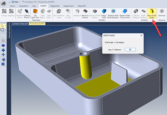 For situations where you cannot dimension a draft angle, or do not want to dimension a draft angle, you can use the Show Draft Angle tool. To use the tool, just select two faces – the pull direction, and the face you are measuring draft for.
In the screenshot at right, the flat plane and a conical face are selected, which activates the Draft Angle button. Clicking on the Draft Angle button causes the Draft Angle dialog to come up, showing the calculated draft value.
Show Draft Angle is particularly useful for showing draft angles that are difficult to dimension, such as the conic geometry shown here.
Cutting Plane (R14 SP1)
Cutting Planes is similar to Section Plane but actually trims back the geometry
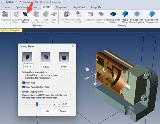 Cutting Planes uses much of the same interface as Section Plane, but with Cutting Planes you are actually trimming away unwanted geometry. Changes are permanent.
In the screenshot at right, the assembly has already been trimmed in the Y axis and X axis. The Clipping Plane is adjustable. The part or assembly will be trimmed and can be saved to a CAD or polygonal format afterwards.
Cutting Planes is useful for isolating the geometry you’re interested in working with as well as revealing the inside of geometry for technical documentation or general visualization purposes.
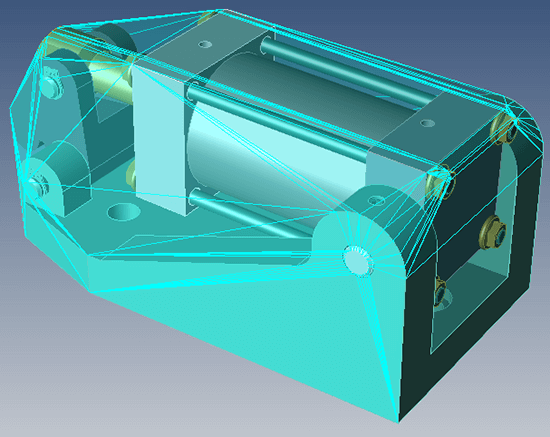
Replace With Bounding Box (R14 SP1)
Replace selected geometry with a bounding box to simplify complex assemblies
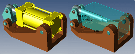 Simply select any geometry you don’t need, and instantly replace it with either a rectangular or convex hull bounding box to simplify and lighten the assembly or hide detail.
All bounding boxes are solid bodies and can thus be used for Mass Properties, Surface Area, Boolean Operations, etc.
Replace with Bounding Box is useful for simplifying large assemblies in cases where you don’t actually need the exact geometry for every part, but you want to retain the general envelope of the part or subassembly you are removing.
Features available in TransMagic MagicCheck
Annotated Change Regions (R14 SP1)
Clearly see all change areas with annotation arrow and label
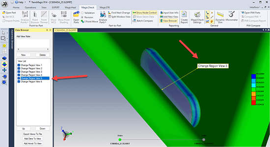 When you click on Find Next Change, or on any view in the View Browser, you will see that every Change Region will have an associated annotation, pointing to the changed area.
Annotated Change Regions are important because as you zoom, pan and rotate to inspect changes, you often need to know which change region is which.
Annotations arrows are only shown in TransMagic, they are not in the MagicCheck report.
See Help > MagicCheck for more information on Part to Part Analysis and Change Regions.
Add Section Views to MagicCheck & MagicCheck Report (R14 SP1)
Now you can see inside the part when generating MagicCheck comparison analysis reports
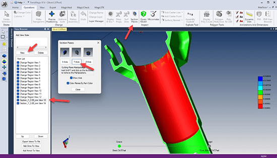 Adding a Section Plane while in MagicCheck will automatically populate into the MagicCheck Report as an additional saved view. Making section views of internal changes is the only way to add them to the MagicCheck report.
In the screenshot at right there are four arrows to show key aspects. Section Planes has been opened from the Operations toolbar, and is being used to create a section in the Y-Axis. This same view has already been saved to the View Browser using the New button, and you can see the specially named view ‘Section_Y_0.00mm_View_13’.
Any views added to the View Browser will be available in the 3D PDF after you create a Report.
Batch Compare (R14 SP1)
Select dozens or hundreds of parts and compare them automatically, in batch mode
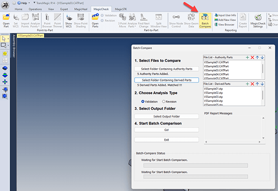 Batch compare allows you to compare many parts at one time, as shown in the screenshot at right. Batch Compare is included with the TransMagic MagicCheck Add-On in Release 14.100.000 and beyond.
To set up Batch Compare, create two folders, one with the original parts, and the other with the derived parts.
Then you just select the folders from the interface, choose an analysis type, select an output folder, and click Go!
Batch Compare will generate a 3D PDF report of all comparisons as well as a log Excel file overviewing which comparisons passed or failed.
(For Reference Only) Features Added in TransMagic R14
New Features Available in All Core Products
Assembly Explode (R14)
Open any assembly and click Explode. Drag the slider for explode distance.
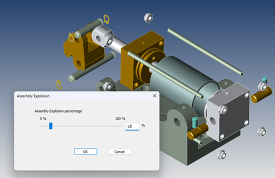 Assembly Explode prompts you to flatten the assembly, and then drag a slider to determine how far to explode the assembly components. The higher the percentage, the further the components will be from each other. Once you click OK, the parts will remain in their new location. Cannot be undone.
Available in all products from the Operations toolbar.
Annotations in 3D PDF (R14)
Bring Dimensions and Annotations into 3D PDF on a Per-View Basis
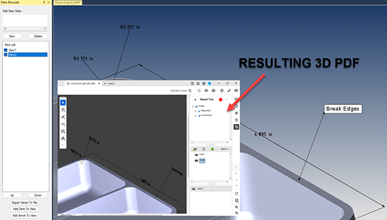 Dimensions and annotations can now be imported into 3D PDF as edges.
Being able to bring CAD metadata into your 3D PDF gives you the capability of even more fully communicating with internal and external teams.
To allow dimensions and annotations in 3D PDF, check Write PDF settings.
In the screenshot, you can see dimensions and annotations applied to the part. Notice that there are two saved views; visibility of dimensions and annotations can be controlled on a per-view basis.
Export BOM (R14)
Export a Bill of Materials for Assembly Parts to an Excel Spreadsheet
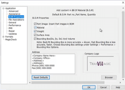 Export BOM, found on the left side of the Home toolbar, will output an Excel spreadsheet with Part Number, Part Name and Quantity as detected in the assembly.
Optional attributes available in TransMagic Settings include:
- Part Image
- Material
- Weight
- Surface Area
- Bounding Box
- Address
- Logo
Industrial Colors (R14)
Colorize now randomly assigns industrial colors to selected geometry
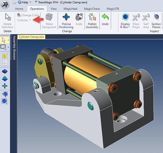 Previously, TransMagic applied completely random colors to models, assemblies and surfaces that did not have assigned colors. These random colors were sometimes hard to see against the default background, or difficult to see detail on (like black), or too similar to selected geometry (selected geometry is yellow), or the CAD assemblies simply looked like toy.
In R14, we have implemented a Colorize button which will change all the selected parts to a random industrial color (typically the color of various metals), and if the model or assembly doesn’t already have assigned colors, ‘colorize’ will be automatically applied to the geometry upon opening the file.
There is a drop down for Colorize called Colorize With Random Color, which will apply completely random colors to all parts and surfaces.
Add Centerline (R14)
Add Centerline puts a centerline in any selected cylindrical face
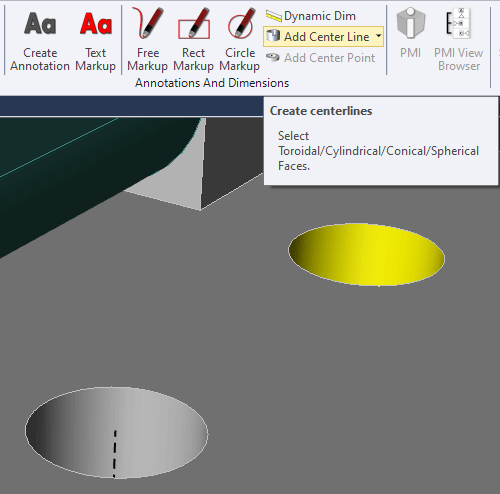 In the screenshot at right, one centerline has already been added to one of the holes, and the cylindrical face of another hole has been selected. Any selected cylindrical face activates the Add Center Line button. Once the button is clicked, the center line will be added.
There is a drop down arrow which makes the center line ‘Render On Top’ so that it renders on top of the surrounding geometry. The ‘Render On Top’ will not actually occur until you click in the screen area again. To turn off ‘Render On Top’, just select a cylindrical face and click ‘Add Center Line’ again.
If you Redraw the screen, the centerlines lose their dashed line type. To get the dashed linetype back, select a cylindrical face and choose Add Centerline again. Centerlines can be deleted from the Assembly Browser.
Show Origin (R14)
Show Origin will display an origin axis on the screen
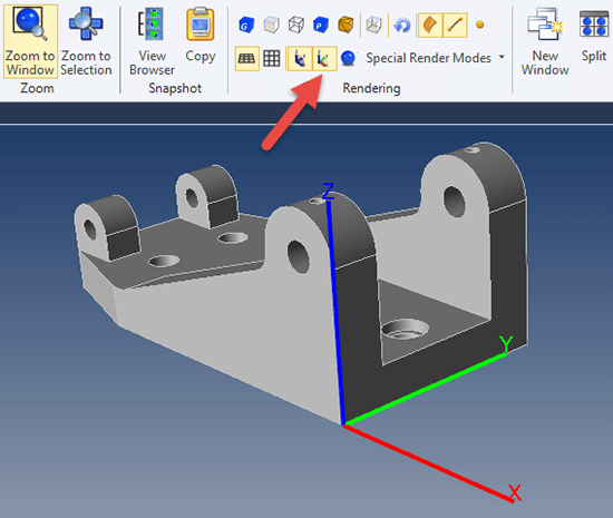 Show Origin can be found on the View toolbar under Rendering (see red arrow in screenshot).
Clicking on Show Origin will cause a red-green-blue axis to be drawn where the origin of the part is located.
You can adjust the size of the origin axis in Settings under Application > Appearance > View Settings > Origin Axis Length (mm).
Show Origin is useful for changing the origin if you want to put the origin in a different location, for example at the center of a hole for machining or measurement purposes. This feature works well with Move to Origin, Add Centerpoint, and Precise Positioning.
Add Centerpoint (R14)
Add a centerpoint to any selected arc or circular edge
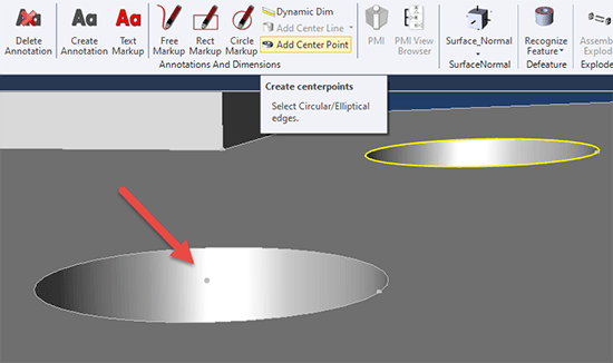 The Add Center Point button becomes active when you select a circular or arc edge. You can select edges using the Single Select tool set to Dynamic or Edge. Once you press the button, TransMagic will place a vertex at the center of the selected edge. However, you will not see the vertex unless your vertices are turned on (View toolbar > Rendering > Show Vertices).
In the screenshot at right, one center point has already been added (indicated by the red arrow), and another circular edge has been selected, activating the Add Center Point button.
Add Center Point can be used with Show Origin and Precise Positioning > Move to Origin to move the center of any arc or circle of any model to the 0,0,0 origin for machining or coordinate measuring machine (CMM) purposes.
Show Surface and Vertex Normals (R14)
Display surface and vertex normal on selected geometry
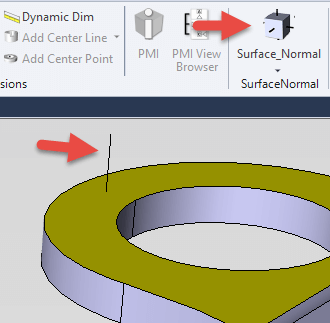 Surface normals indicate the positive direction of any selected surface. In the screenshot at right, the yellow face is selected, and then the Surface Normal button is clicked. This creates the black ‘normal’ line on the selected face, indicating the positive direction for that surface. Occassionally, you will run into geometry where one or more surfaces have inverted normals, and Surface Normal is one way confirm inverted normals.
You can also select any edge or group of edges, and use the drop down arrow under Surface Normal to create Vertex Normals at the vertices of any selected edges.
To make surface normals go away, just select the same geometry again, and click Surface Normal again; in that sense, the Surface Normal and Vertex Normal buttons are on/off toggles.
Convert T-Edges to Edges (R14)
Tolerant Edges can now automatically be converted to edges
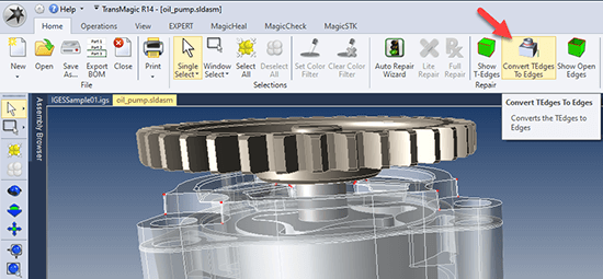 Tolerant Edges are edges on CAD models that are within acceptable range, but are less than TransMagic native precision. These edges can be seen by clicking on the Show T-Edges button.
If you use Convert TEdges to Edges, you improve the quality of geometry for better downstream results; for example, we have seen several instances of geometry which could not be saved out to a CATIA format without first converting TEdges to Edges.
Features in both TransMagic EXPERT & MagicHeal
Defeaturing: Recognize and Remove Features (R14)
Hide IP, simplify parts and assemblies for better performance
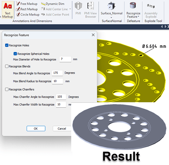 Features including holes, fillets and chamfers can be recognized and/or removed based on size and angles. Recognized features will have their faces highlighted in red.
The drop down for Recognize Feature is Remove Feature; the same features which were ‘recognized’ can be removed with Remove Feature. Use Recognize Feature if you want to see what the impact on the part or assembly will be, and use Remove Feature if you already feel confident of the result you will get.
In this example, we are only removing the holes recognized in the previous screenshot.
Blends (fillets) and Chamfers can also be removed using this tool – values should be given in mm and degrees.
Atomize (R14*)
Atomize turns any CAD or polygonal assembly into discrete parts
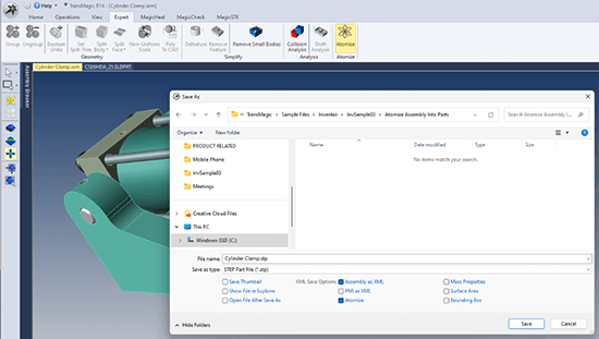 In the screenshot at right, Atomize has been clicked, and it opens the Save As dialog box with Assembly as XML and Atomize enabled. Notice in this case that the STEP format is the currently selected format in the Save As type. As soon as you click Save, the assembly will be saved to the desired location as discrete STEP parts.
STEP and Parasolid are typically a monolithic assemblies, but by using Atomize, you can save the discrete parts to the folder of your choice. Some customers use Atomize to generate separate STL models for individual 3D print processing.
Notice also that you can save out XML data for PMI, Mass Properties, Surface Area and Bounding Box by checking the relevant boxes. This XML data will be saved to the same folder as your CAD or polygonal files.
*Atomize was introduced in the R12 timeframe, but the Atomize button was added in R14.
Compare PMI (MagicCheck R14)
Select two parts with PMI and Compare their PMI
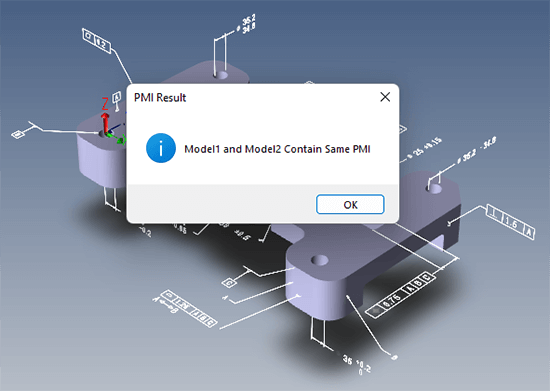 Open two models which contain PMI notes using Open PMI Parts. Click Compare PMI, and you’ll receive a message that the PMI either matches or does not match.
For further feedback, you can click PMI Compare Report to see an Excel spreadsheet detailing which PMI notes were in sync and which were either missing or conflicting from the Source part.
For PMI comparison to work, the PMI must be semantic, not just graphical. See more on Compare PMI in Help.
MagicSTK (R14) – For Ansys/AGI STK Users
MagicSTK allows you to convert geometry to Collada or GLTF for use in STK flight simulations
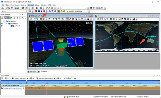 MagicSTK is a new TransMagic Add On which prepares CAD or polygonal geometry for use in the Ansys/AGI STK (system tool kit) flight analysis & simulation software.
The screenshot at right is from an STK satellite orbit simulation. Attach points can be applied for positioning of cameras as shown in the left-most image. Solar panels can be designated, including efficiency percentages and the ability to rotate around a given axis.
MagicSTK began life as an Add On in R14.
GLTF format support added in R14 SP1
How to get R14 SP1
You can find both the latest version of R12 and R14 at https://TransMagic.com/download/
Please Note: R14 is available to all subscription customers and perpetual customers with current maintenance as of June 1, 2023. If you are a perpetual customer whose maintenance has expired before June 1, 2023, do not install R14 since it will not run and will require a clean uninstall of R14, a device clear process, and reinstall of R12. If you are a perpetual customer who would like to renew your maintenance, please contact sales@transmagic.com.
Installation Instructions: Installing TransMagic R14 SP1 – TransMagic Support Center