CAD Comparison is one of the most important and least understood areas in design and engineering today. Comparison software automatically evaluates the exact degree to which two models have the same geometry, provides a method to authenticate that the two models are the same for all practical purposes and determines how well a grouping of points fits to an existing 3D CAD model. TransMagic’s CAD Comparison solution is MagicCheck.
A Bigger Problem than Perceived
How does an estimator or designer quickly check that the revision the customer just sent actually only has the specified changes, and that there are no ‘surprise changes’ elsewhere in the file? How does purchasing make sure the part they ordered is the same as the part they received? When translations have taken place for downstream analysis or machining, how does a company guarantee that the files are actually the same, within a specific tolerance? Without the answer, the risk is that downstream there will be expensive surprises. In fact, one study found 15% of the time, CAD errors were not found until parts had already been cut1.
Easy Part to Part Comparison
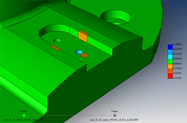 The most basic use of CAD comparision software is to compare two parts; how easily is the comparison achieved? Can the software allow the user to see inside the parts where changes may be hiding? Are degrees of tolerance up to six places available? Will the software display a color plot showing all changed features and their degree of change? Is a report generated automatically?
The figure at right shows an example of two parts being overlaid and compared; note the color ‘heat map’ that helps the eye distinguish geometry that is unique to each revision, as well as how far out of tolerance each variation is.
Part Authentication
 How can you be certain that the part you translated to STEP for your analysis is within a reasonable tolerance to the original part dimensions?
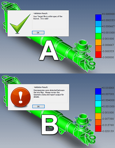
This is a problem that many aerospace firms are forced to deal with, and a problem that companies such as Boeing take a keen interest in. Suppliers to Boeing and other aerospace OEMs are tasked with proving that their derived models have not significantly changed from the original sent them by the customer, via Boeing validation document D6-51991.
Section 7 of aerospace spec AS9100 is concerned with verification and validation procedures, many of which are answerable with validation tools such as MagicCheck.
CAD comparison software can authenticate two parts, comparing the original master model and the derived check model to determine how close they are in hundredths, thousandths, or ten-thousandths of an inch or millimeter. The screenshot at right shows an example of a passed validation analysis, and a failed validation analysis.
See an example of how CAD model validation works in the video below.
Point to Part Comparison
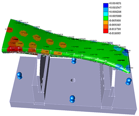 CMM and other scanning devices return a list of X, Y, & Z points of physical prototypes or production parts. Using Point to Part Comparison, these points can be compared to the original CAD master model to see how closely the physical model matches.
In the figure at right, a colored ‘heat map’ shows which points are within the specified tolerance (anything green is within tolerance), which points penetrate into the master model envelope (warm shades such as red), and which points are outside of the part envelope (cool colors, i.e., blue).
Know your CAD Data
TransMagic MagicCheck not only compares and authenticates part-to-part and point-to-part geometry, but it provides a single-button report, specifying where the geometry is within tolerance and out of tolerance, complete with custom views and ‘heat maps’ views.
With MagicCheck, you’ll know when your customers have made additional ‘undocumented’ changes to part geometry. You’ll be empowered to authenticate that your working geometry is within tolerance to the master model geometry, thus enabling you to go after a wider range of customers. And you’ll be able to compare scans and CMM data to the original part, in order to find and effect adjustments to the manufacturing process so that final products conform to the right dimensions & assemblies go together properly. Learn more about TransMagic MagicCheck here.
1 1999 Interoperability Cost Analysis of the US Automotive Supply Chain
Request a 7-Day TransMagic Evaluation
Evaluate TransMagic for 7 days to see how it works with your parts!
Subscribe to Newsletter
Never miss a newsletter or a special offer from TransMagic!
TESTIMONIALS
Desktop Engineering
– J. G., Desktop Engineering
Stark Manufacturing
– M. G., Stark Manufacturing
BRC Rubber and Plastics
– P. P., BRC Rubber and Plastics
What’s New