CAD Interoperability
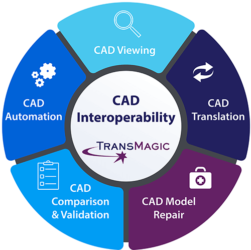 CAD Interoperability is critical in today’s multi-CAD world.
CAD Viewing is an important part of CAD interoperability because sometimes you just need to view a CAD file which originated in another CAD system. In some cases it’s a customer file you need to use to generate a quote. For that, you need access to all major CAD formats, and the ability to dimension, interrogate, and access CAD data like PMI and UDA.
CAD Translation is perhaps the most important aspect of CAD interoperability because you often need to translate from one format to another, and you’ll want the very best translation you can get, lest your CAD geometry lose fidelity, or you lose CAD data.
CAD Model Repair is also critical because if the original model was poorly modeled, or if the translation introduced issues, either because the translator was poor, or because the formats were too different – the file needs to be repaired, or replaced. Sometimes repair issues can be sidestepped by rethinking the formats you’re using, or by asking the customer for a new file. But when repair becomes necessary, automatic repair tools are obviously going to be faster and help keep the project on track and within budget.
CAD Comparison & Validation are both important because you need to know what changes your customer has introduced into revisions so you can maintain control of the quote and the finished product; and if you’re doing work for Boeing or other aerospace firms, you may need to validate that the derived CAD file you’re working with is within tolerance of the original CAD model they gave you.
CAD Automation is the automation of processes – whether that means translating 1000 files at a time in batch mode; or giving entire teams access to instant translation, so that the important design and engineering work can go on unhindered; or simply automating repair processes.
All of these aspects to CAD interoperability are important; but CAD interoperability still starts with making sure that you’re getting and giving the best quality CAD models and data possible.
Get the Best File Possible
When possible, ask your customer for the native CAD file. The native CAD file, whether it is CATIA, NX, Creo, Solid Edge, SOLIDWORKS, Inventor, AutoCAD or something else, is always the best place to start. That is, assuming you can read the native format (which all core TransMagic products can do).
If you can’t get the native file, try to get the geometric modeling kernel file. If your customer is using NX, that would mean asking for the Parasolid file, because NX CAD files are built using the Parasolid kernel as a foundation.
If you can’t get the native or the kernel format, STEP is your next best choice. See the article Choosing the Best CAD Format for more on this subject.
Access the CAD Data You Need
It’s not always just the CAD model that’s important; the CAD data is equally important. This can include File Information, User Defined Attributes (UDA), Product and Manufacturing Information (PMI), File Properties (such as mass properties, surface area, etc.) and even extracted CAD data.
UDA and PMI can be read from native CAD formats as well as STEP AP242, then shared easily with project stakeholders via a Technical Data Package (TDP). See an example of how to use TransMagic’s Tech Docs TDP, and how to extract CAD data to XML.
Know Your CAD Data
If the customer sends you a part to quote for tooling, you know exactly what to do. But if they later send you a revision, how do you know what changed? Some designers have adopted the practice of opening both parts, coloring one green and one red, and visually inspecting them to verify any changes. This can work when the changes are large, but the risks are high if you miss a small, seemingly insignificant change the customer failed to mention; you might create a erroneous quote, or even cut a part that doesn’t work with the rest of the assembly.
CAD revision analysis makes it easy to see exactly what has changed between revisions, and it only takes seconds to set up. For more about CAD revision analysis, see the article Revision Checking – Brute Strength vs Automation.
CAD validation analysis is a similar process, but with CAD validation analysis, you are testing the original CAD model given to you by the customer against any translated copies of that file you may have used in your design or manufacturing process. The idea is that your customer may ask you to validate that the changes between the two files are less than .005 inches (the allowable tolerance may vary). Validation analysis will quickly determine if your derived model is within tolerance, and create a report showing that it either passed, or in the case where it did not pass, exactly where the problems were, and how far out of tolerance they were. Read more about CAD model validation here.
CAD Interoperability Links
- CAD File Extensions – A listing of all known CAD file extensions
- Which Geometric Modeling Kernel – A listing of CAD applications and the kernels they employ
- CAD Formats – A listing of all the CAD formats supported by TransMagic products
- Brep vs Visrep Models – A comparison between true CAD Brep models and polygonal Visrep models
- What CAD Format – How you can detect which format and version you have using a text editor
- Choosing the Best CAD File Format – Finding the best format using the CAD Format Ladder
- What is CAD Data? – The forms and uses of CAD data
Specific CAD Formats
- IGES vs STEP – Reasons you might choose one over the other
- How to Open a JT File – Considerations when opening JT
- CATPart to STEP – How to convert CATIA CATPart files to STEP
- Parasolid to STEP – How to convert Parasolid kernel files to STEP