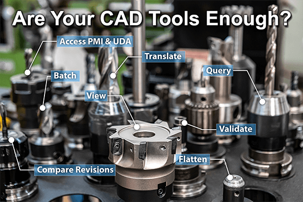
Are your CAD tools empowering you to…
 Work faster and more efficiently? We have customers who have saved hours every week by batch translating, or simply converting massive assemblies to multibody parts for easier insertion into CAD PDM systems.
What could speed your processes up?
Below is a list of 22 ways TransMagic can help you get the job done fast.
Take a moment to scan through these capability high spots of TransMagic products to see if you’re leaving any time on the table!
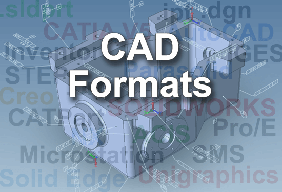
1. View All Major CAD formats?
 All core TransMagic products can view CATIA, NX, Creo, Pro/E, Solid Edge, SOLIDWORKS, Solid Edge, Inventor, DWG, Microstation, Parasolid, ACIS, SMLib, STEP, IGES, VDA-FS, 3DXML, Obj, Collada, PLY, POD, STL, U3D and VRML.
TransMagic gives you the power to read your CAD files with the best, licensed technology possible, so that you get the best possible CAD geometry to work with, minimizing missing geometry, repairs and rebuilds.
Access to a wide array of CAD formats also gives you increased flexibility to deal with more customers, and gives you more options when accepting CAD data from others.
Viewing of all major 3D CAD formats is standard in all core TransMagic products.
2. Access CAD Data?
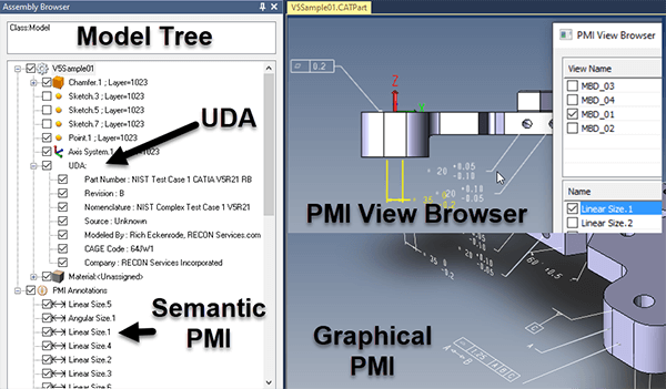 View User Defined Attributes (UDA), Product and Manufacturing Information (PMI). See semantic PMI in Assembly Browser or graphically on main screen. Highlight specific PMI notes from the Assembly Browser or via the PMI View Browser.
Export 3D CAD models out to 3D PDF, include all selected PMI views. Select and change PMI color and screen background.
Learn more about PMI here.
UDA and PMI tools are standard in all core TransMagic products.
3. Dimension and Interrogate Models?
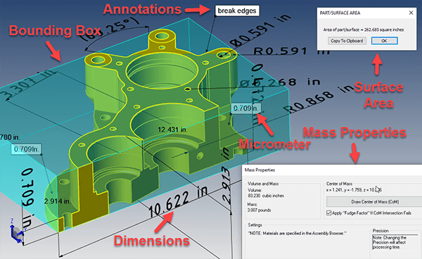 Dimensioning is as easy as clicking an edge, vertex or face, and placing the dimension. Hole to hole dimensions. Annotations and Markup. The Micrometer tool lets you measure thicknesses.
Interrogate for Mass Properties (mass and volume), Surface Area and Bounding Box. Determine Edge Length. Select materials per part and add custom materials. Control which dimensions appear in saved views.
Dimension and Interrogation tools are standard in all core TransMagic products.
4. Adjust Transparency and Sections?
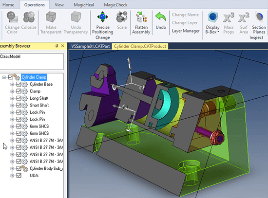 Easily change component colors and transparency.
Cut sections in X, Y and Z directions at any angle.
Single Select or Window Select vertices, edges, faces, PMI, bodies, solid bodies, surfaces or wire bodies.
Define and control visibility of layers. Select All, Deselect All, Hide selected, Show All.
Render to goraud shading, hiddenline, wireframe, phong plus eight special render modes.
Preset yet flexible orthographic views. Name, save and restore custom views.
All viewing tools are standard with all core TransMagic products.
5. Stitch Surfaces into Solids?
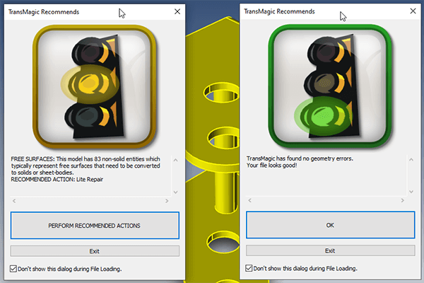 If you get an IGES file, it is almost always composed of surfaces. These surfaces need to be stitched together in order to form a watertight solid. Solids are preferable to surfaces because it’s easier to process a single part in a CAD system as opposed to dozens or even hundreds of surfaces.
When you open a file in TransMagic, the Auto Repair Wizard (ARW) instantly analyzes the geometry; as shown in the image at right, if there are surfaces, it tells you how many there are and gives you the option to stitch them into a solid, which is handled by Lite Repair. At far right you can see the result; a green light indicates a watertight solid.
In addition to Lite Repair, there is a Full Repair which handles more extreme issues and is available as part of the MagicHeal Add-On.
Lite Repair comes with all core TransMagic products.
6. Improve CAD Geometry Quality?
 Basic Geometry Repair
If you have zero length edges, zero area faces, negative area faces, duplicate vertices or duplicate edges, Lite Repair can sort these out and return a healthy, watertight solid.
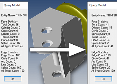
Replace Splines with more precise Analytic Geometry
Depending on the history of your CAD data, they may be composed primarily of splines. A spline is not as accurate and precise as analytic geometry. Examples of analytic geometry include lines, arcs, planes, cylinders and spheres. A hole can often be best described as a cylinder, for example. If the hole is described wih spline mathematics, a downstream CAD application may not recognize it as a hole as easily as if it were described with the more precise analytic geometry.
To convert spline geometry to analytic geometry, simply select a part this is already a solid model, and run Lite Repair on it. If the model is composed of surfaces, you have to run Lite Repair twice; once to stitch it into a solid, and once to refine spline geometry to analytic geometry. Not all geometry can be described with analytic geometry, so Lite Repair will do the best job it can with whatever you throw at it. In most cases, however, you will find that a large percentage of edges and faces are converted.
Lite Repair is standard with all core TransMagic products.
7. Flatten or Create Assemblies?
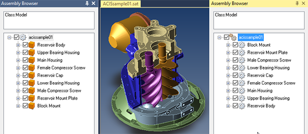 Sometimes it is critical to convert assemblies to parts, either to satisfy CAD application requirements, or to speed up otherwise tedious processes using CAD applications with PLM software. Flattening is a single-step operation where you simply click on the Flatten button on the Operations toolbar. At near right you can see an assembly in a flattened state – all of the parts have been converted to solid bodies in a single part. In TransMagic, parts are denoted by a single gear, assemblies are double gears, and solid bodies are orange cubes.
Just as sometimes the downstream CAD application requires or prefers a part, at other times it needs to be a true assembly. This is easy to accomplish with any single part or multi-body part. At far right you can see an example of an assembly that was generated from a multi-body part.
Other assembly restructuring tools include the ability to create new subassemblies, rename parts or subassemblies, and break instances so that they are independent of each other.
Assembly restructuring tools are standard in all core TransMagic products.
8. Write to Polygonal Formats?
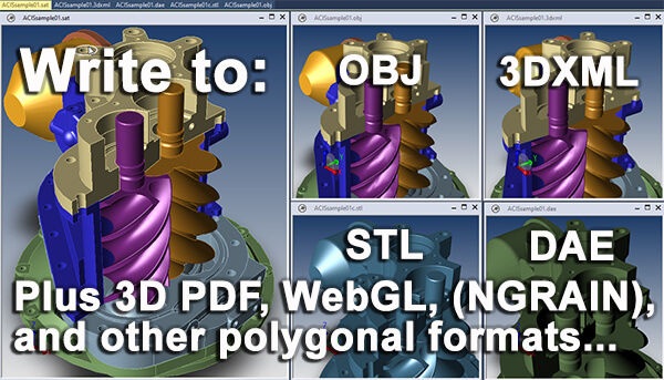 Polygonal formats include WebGL, 3D PDF, Obj, STL, POD, 3DXML. STL is useful for 3D printing, Obj and Collada are useful for arts & entertainment industries, and 3D PDF and WebGL are useful for capturing your CAD model and any associated PMI to project stakeholders who may not have access to CAD or CAD viewers.
Read more about polygon optimization.
Write to polygonal formats is standard in all core TransMagic products.
9. Write to Neutral and Native CAD Formats?
 TransMagic can write to native CAD formats such as CATIA, JT and DWG, kernel formats such as Parasolid and ACIS, and neutral CAD formats such as STEP and IGES. TransMagic PRO writes to kernel and neutral CAD formats, and TransMagic EXPERT write to neutral, kernel and native CAD formats.
Having TransMagic in your tool belt gives you an additional way to write to the formats your customers need, as well as giving you access to the latest CAD formats and versions, even if you’re working with an older CAD system.
See the CAD Formats page to learn which core products write to which formats.
10. Publish Technical Data Packages?
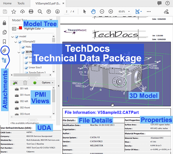 A technical data package (TDP) is a 3D PDF of the model or assembly that even non-CAD users can view, rotate and measure, along with User Defined Attributes (UDA), Product and Manufacturing Information (PMI), mass properties and surface area values, materials descriptions, a model tree, as well as attached files.
Attached files can be the original CAD format, additional CAD formats, polygonal models, Excel spreadsheets, Word docs, images and animations. In short, any data that is key to the project can be attached to a TDP.
The beauty of a TDP is that it gives you all the pertinent CAD data in one tidy PDF file – everything is included. No emails with multiple attachments, no missing documents, no multiple emails and missing files, no need for CAD viewers or translators.
TransMagic’s version of TDP is called Tech Docs. Tech Docs gives you all of the benefits of a TDP and adds the ability to select the CAD formats you want to be included in the TDP, and when you click the ‘Go’ button, the translations begin; whether you selected three or seven formats, the translation is automatic, and doesn’t stop until your 3D PDF, with selected files attached, is complete.
This means you can setup a large TDP before lunch and let the software translate and attach the files in an unattended batch mode, saving you time.
Learn more about Technical Data Packages and watch a TDP video.
Tech Docs is available in TransMagic EXPERT.
11. Convert Polygonal Geometry to CAD Geometry?
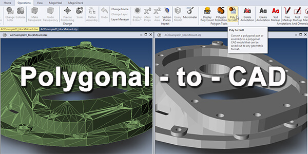 When you need polygonal geometry to be converted to true CAD Brep geometry, how can you do that? It’s as simple as pressing the Poly To CAD button in TransMagic EXPERT. Each polygon triangle creates a boundary representation face, which can make for a large file.
For this reason, it’s important to get your faceting settings right. You have excellent control over the density of the faceting via the Polygon Reduction slider and advanced polygon output settings.
Read more about Poly to CAD.
Poly to CAD is available in TransMagic EXPERT.
12. Atomize Components from Assemblies?
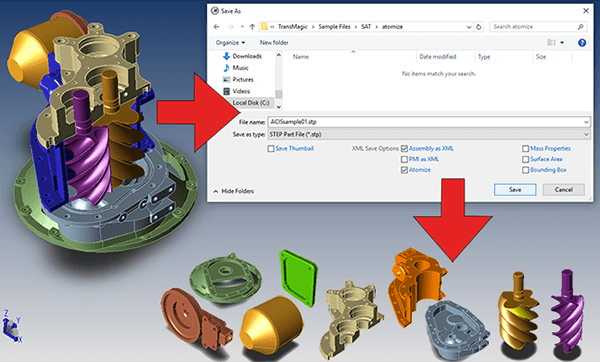 ‘Atomizing’ is the process of converting selected assemblies to individual components in the format of your choice; each component gets converted to STEP or STL or whatever format you choose.
If for example, you have a CATIA or SOLIDWORKS assembly and you want to convert each of the component parts to STL for 3D printing, it’s as simple as making sure that ‘Atomize’ is checked and then selecting STL as your format before you click Save As. This is far easier than opening each component separately and saving out to STL. Atomize can be used for any format TransMagic can write to.
Read more about Atomization.
Atomize is available in TransMagic EXPERT.
13. Extract CAD Data to XML?
 Extract assembly information, mass properties, surface area and PMI information from parts and assemblies into XML. XML information extracted from CAD models and assemblies can be useful for bill of materials, parts lists, cost estimates, and can serve as a tool to build and understand the digital thread.
At right is an example of extracted Production and Manufacturing Information (PMI) along with a screenshot of the GD&T being highlighted. On line 1 you can see that this is ‘graphical pmi’. On line 10 you can see the value of the dimension in mm, and on lines 15 and 20 you can see the positive and negative tolerance applied to the diameter.
To extract CAD data to XML, click Save As and check the boxes for each type of CAD data you want to extract, and click OK. Read more about CAD Data Extraction.
XML CAD Data Extraction is available in TransMagic EXPERT.
14. Perform Boolean and Non-Uniform Scaling Operations?
 Boolean operationsallow you to Group components, union solids and subtract solids from each other to produce new solids or simply cut faces, using split/trim (see image at right). Learn more about Split/Trim here.
Non-Uniform Scaling gives you three directions to assign new values to (as shown at far right).
Boolean operations and non-uniform scaling are available in TransMagic EXPERT.
15. View Parts and Assemblies Quickly?
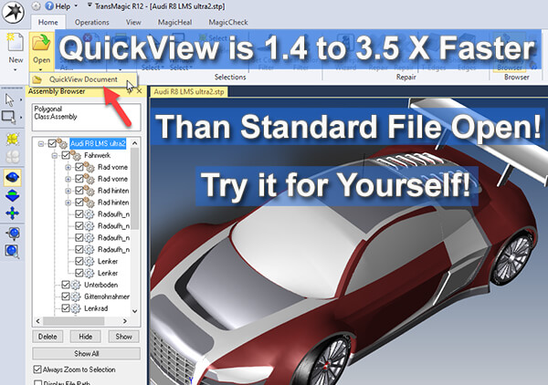 Using new QuickView technology, open large parts and assemblies significantly faster than normal; this can save an enormous amount of time per workstation. Instead of selecting Open, use QuickView Document. The part or assembly will open and can be rotated, zoomed, panned, and the contents of assemblies can be viewed in the Assembly Browser.
At any time, you can select the compoent or subassembly of your choice from the Assembly Browser and use the Right Button Menu option ‘Open Precise’ to open the geometry of interest. Geometry that is opened with QuickView Document cannot be edited, dimensioned or interrogated in any way, whereas geometry that is opened with Open Precise can be edited using all of TransMagic’s normal features.
QuickView is part of TransMagic EXPERT, but is temporarily available in all core TransMagic products as ‘Preview Technology’.
16. Automatically Repair?
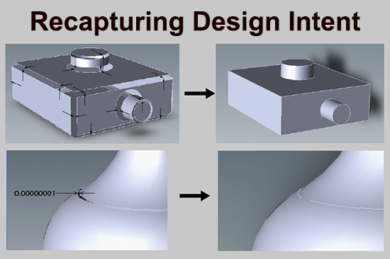 CAD modeling processes and errors during translation can sometimes cause gaps and non-tangencies to form between model faces. Some translation errors are inevitable due to the different precisions of each CAD system and the different ways each system implements different features. These geometric issues can cause the model to be corrupt and non-watertight.
In both cases shown at right, it is obvious that the plan was for a box where the edges meet, and a tangent bottle profile. In the case of the box, the original box planes are extended until they intersect, closing the gap. In the case of the bottle, the surface is analyzed, and snaped into place to created a tangent profile. Both examples are exaggerated graphically for illustrative purposes. Full Repair in essence recaptures the original design intent for fully enclosed, tangent solid models.
Full Repair also manages some more advanced problems such as inverted vertices. Learn more about Full Repair here.
Full Repair is available as part of the MagicHeal Add-On.
17. Replace Bad or Missing Surfaces?
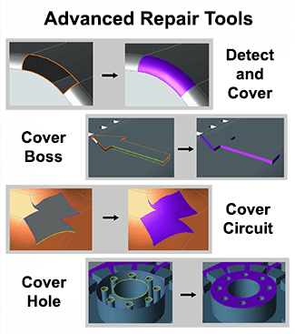 Sometimes the file you received from a customer is missing a face, or several faces. While we’d first advise making sure you’re getting the best file and translation possible to avoid damaged or corrupted files, sometimes you have to make the best of what you have, and in many cases those missing and corrupt surfaces can be replaced quickly and easily using tools which allow you to select an edge on an open area and cover it with a new face.
The figure at right illustrates some of the ways you can generate surfaces based on surrounding geometry.
MagicHeal also includes Full Repair, which can automatically assess and repair advanced problems such as inverted vertices.
This surface replacement capability is part of the MagicHeal Add-On.
18. Compare Revisions?
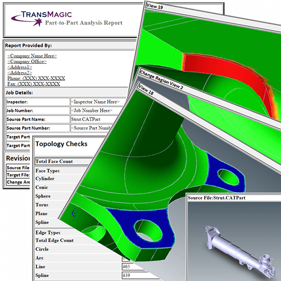 Do you ever wonder what’s changed between customer revision A and revision B? They say that only the hole size has changed, but what if there were more changes they neglected to mention? That could change the quote for tooling, or could lead to problems with production.
Some users have a ‘Red/Green technique for spotting changes, coloring revision A green, and revision B red, then putting them both in the same CAD session and looking for differences between them, either in wireframe or shaded render mode. This method worked reasonably well in the past, but its weakness is that it is hard to see very small changes, and it leaves too much up to human error.
CAD Revision Analysis software makes it easy to see what changed between two revisions by allowing the user to set a part to part tolerance; anything that is not within the set tolerance gets highlighted in red or green (red for areas where the changes would cut into the original part envelope, and green for areas that are outside of the original part envelope).
You can compare the two parts separately, or overlapping each other, and you have the ability to create an automatic Revision Analysis Report, which highlights the areas outside of tolerance.
Revision Analysis is available in the TransMagic MagicCheck Add-On.
19. Validate CAD Models?
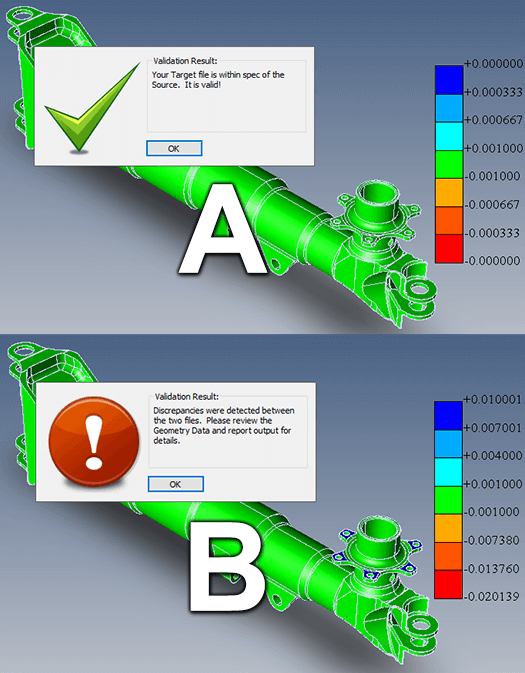 CAD Model Validation tests the original CAD authority model against derived (or translated) models to verify that they are within a 0.005 (or some other tolerance).
Model validation is one aspect of Boeing spec d651991, which their suppliers must conform to; this ensures that the model the customer gave to the supplier is essentially the same as what the supplier worked with when establishing designs and products.
If the derived CAD model is within tolerance, it is given a pass; if there is any geometry that is not within tolerance, the area is colored red or green to indicate where and how far out of tolerance it is.
Like revision analysis, validation analysis gives you the option to generate an automatic report, which tells if the validation analysis was within tolerance or not, and points out areas that exceeded the specified tolerance.
Learn more about Validation Analysis, and Boeing spec d651991.
Validation Analysis is available with the MagicCheck Add-On.
20. Perform Point to Part Analysis?
 Point to part analysis allows you to compare CMM data to the original authority CAD model, so you can see clearly how close each scanned or measured point is to the actual 3D model.
Points that within your selected tolerance are green, but colors outside of the allowable tolerance are either shades of red or blue; red points cut into the original model envelope, and blue points are outside of the original model envelope.
Like Revision Analysis and Validation Analysis, Point to Part Analysis will automatically generate a report; you can also use the Point Browser to show exact XYZ locations for each point, and use the Point Thinner if there are too many points to work with.
This analysis can help you understand where you may need to adjust a manufacturing process (like molding) or where you may need to revise the CAD authority model to account for stretching or variation due to manufacturing processes.
Point to part analysis is available with the MagicCheck Add-On.
21. Batch Translate?
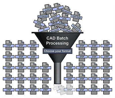 When you have a lot of CAD translations to do, it can be tedious – the user has to find each file, wait for it to open up, then Save As to the format of choice, and wait for it to save before repeating the same process for each file to be translated. Traditional Open and Save As processes waste a lot of time for the user and tie up the machine. A better solution, if there are many files to be translated, is to batch translate.
Batch Translation involves selecting all the files (parts or assemblies) you want to translate, then selecting the format you want to convert them all to, the folder you want to save them to, and adjusting any desired settings. Then you just click Go! Hundreds or even thousands of files can be translated automatically this way, without the need for user intervention. Batch translation can be done at any time – some users run batch translations in the evening or over the weekend.
Batch Translation is available with the MagicBatch Add-On.
22. Access Enterprise CAD Automation?
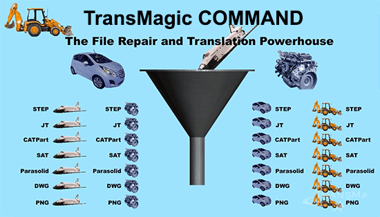 One of the biggest hassles design and engineering teams can run into is getting the CAD data in a format that is consumable for them in a timely way; sometimes they have to wait on the guy in the department who is responsible for translations to do it for them, and sometimes they have to do it themselves, stealing compute cycles and valuable minutes from their other design tasks.
Imagine entire departments being able to place CAD files into a ‘Translate’ folder on the intranet, and every file in that folder being automatically translated into four different CAD formats automatically within a few minutes (this is illustrated in the graphic at right, although you can actually translate to as many different formats as you like, simultaneously). Optionally, files can be repaired as they are translated.
This kind of automated service is possible by combining TransMagic COMMAND with the Windows Folder Monitor, though a simple script. TransMagic’s sample script is written in VB, but you can use any language you like.
Typically, this enterprise solution is managed by the IT department for engineering and design teams. Setup is fast and easy, and waiting on translations becomes a problem of the past for everyone who has access to the drop folder.
COMMAND is a special TransMagic application. Learn more about COMMAND.