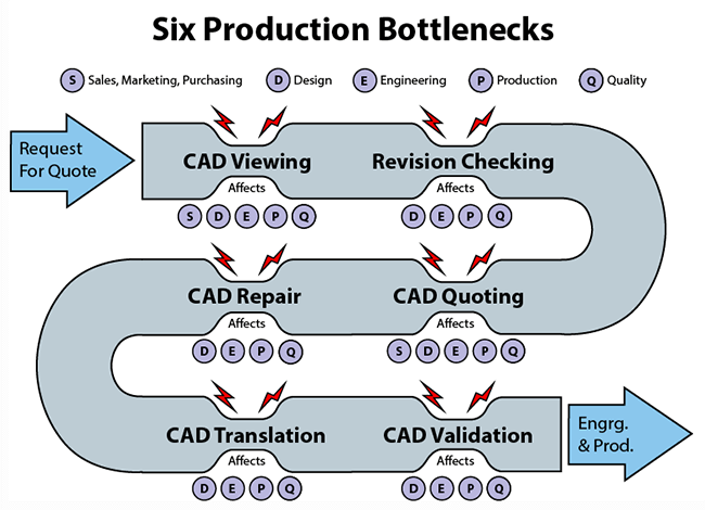
 Normally, we think of production bottlenecks as occurring on the production floor; but there are upstream processes which can delay production as well as adversely impact manufacturing, quality assurance and scrap.
CAD Viewing
The inability for all project stakeholders to view and interact with CAD model data can become a production bottleneck, because 3D part and assembly models give the entire team a window into the project which could trigger necessary interventions early in the production process, before they become prohibitively expensive.
CAD Viewers and 3D PDFs – This doesn’t mean all stakeholders need a full CAD seat, however; they might just need access to a CAD viewer, or even access to a 3D PDF of the model or assembly. CAD viewers are typically much easier to operate, with far lower training and maintenance requirements than full-blown CAD systems. Network installations of viewers can be accessed on an as-needed, on-demand basis, and 3D PDFs can be viewed, zoomed and rotated in 3D as long as Adobe Acrobat is installed.
The 2013 3D Collaboration Interoperability Report found that:
- Over 47 percent of engineering organizations exchange both native and neutral CAD formats with both customers and suppliers.
- The most frequently used native formats were Creo, CATIA, NX, SOLIDWORKS and Inventor.
- The most frequently used neutral formats were STEP, IGES, Parasolid and JT, in that order.
The takeaway is that the design and engineering environment is becoming increasingly multi-CAD, and it’s important to be able to read as many native and neutral CAD formats as possible, to be able to serve existing customers as well as expand operations to serve new customers. Some of the areas which could benefit from CAD viewing capability include sales, marketing, purchasing, design, engineering and production.
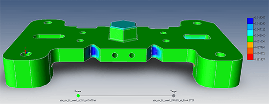
Figure 1 – Revision Checking helps you see what changed easily and quickly.
Revision Checking
Knowing What Changed – Even today, many designers and engineers are using brute-force revision checking methods to determine if there are any hidden or missed changes between CAD model revisions. One of our customers estimated that over seventy percent of CAD models received from his clients had undisclosed revisions. Typical methods of comparing revision A to revision B is to color one red, the other green, and then insert revision B into revision A so they overlap, and then look for differences visually. While this method might suffice for more obvious differences, it will not catch very small variations in model topology. With revision analysis software, you select the allowable tolerance, and let the software do the heavy lifting; most revision analysis software will generate a heat map which makes areas outside of tolerance visible, so that all changes are made clear.
The Cost of Missed Changes – Without quality revision checking, there is the possibility that hidden changes will be missed, and not included in the final produced product, which could derail the project, damage the relationship with the customer, and lead to increased scrap. Another possibility is that hidden changes are included in the final product, but because the changes were hidden, the costs were not properly estimated and the company again takes a loss.
A survey by PTC exploring 2D and 3D CAD Trends in Product Design found that out of 7,019 respondents:
- 44 percent experienced excessive, unanticipated changes throughout development.
- 9 percent experienced dramatic or multiple last-minute changes to product specifications.
Excessive, dramatic changes in the manufacturing environment can create conditions in which the wrong parts are being manufactured, there is less time to inspect parts for hidden changes, and the later changes happen in the process, the more tedious and expensive they are to implement. These are all bottleneck factors.
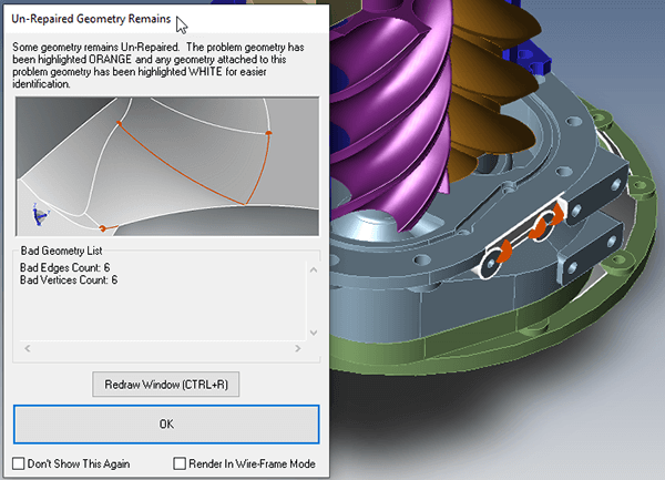
Figure 2 – CAD repair tools can perform diagnostics as well as automatically solving problems like this one.
CAD Repair
Bad CAD Data Is a Prevalent Problem – Corrupt or damaged CAD model data can create a bottleneck which slows down engineering. Whether due to translations from one format or another, or poor modeling practices, it is not unusual to find a problematic CAD model. A 2006 CAD Interoperability Survey by Kubotek involving 2,869 respondents found that:
- 95 percent of all respondents had issues transferring CAD model data between different systems, most often citing missing or corrupt data.
- Regardless of the industry, only about 25 percent of respondents used the originating CAD system to complete design work.
- 34 percent of respondents have to rebuild 3D models from scratch at least half of the time. Another 49 percent have to rebuild models between rarely and up to half the time.
In addition, the 3D Collaboration Interoperability Report found that:
- 49 percent of engineers spent over four hours per week fixing design data.
- 14 percent of engineers spent over 24 hours a week fixing design data.
- 50 percent of engineers work late or on the weekend fixing design data.
- 32 percent of engineers miss project deadlines because of design data problems.
- 29 percent of organizations have ordered incorrect parts due to design data problems.
Each Hour Counts – Each hour spent repairing or remodeling CAD geometry is an hour that design and engineering is not being performed. CAD repair software can in many cases automatically repair damaged CAD models, and in other cases provide interactive tools to help users make repairs more quickly than with ordinary CAD tools.
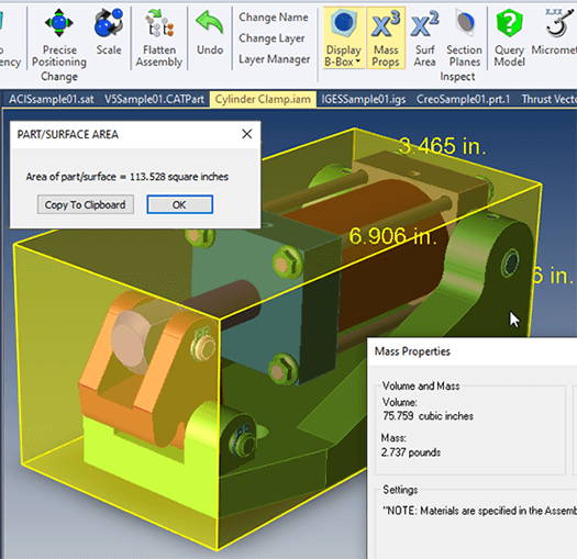
Figure 3 – Models and assemblies can be measured and interrogated.
CAD Quoting
CAD Quoting can be a bottleneck if the estimator is unable to get the file in the format they can view, or if the quoting software is missing critical functionality; this often results in the users creating complex workarounds which further increase estimating time.
It’s important to have access to the actual Brep CAD model for measuring distances, wall thickness, mass properties, surface area, bounding box and other analysis critical to generating an accurate quote. If you’re working with Visrep or polygonal models, your analysis results will not be as accurate.
If you or your customer are using Model Based Definition (MBD), it is important to be able to view and manage Product and Manufacturing Information (PMI) so that notes and geometric dimensioning and tolerancing information is taken into consideration on the quote.

Figure 4 – CAD translation is dependent upon the optimal format, quality translators and tuned settings.
CAD Translation
The Need for On Demand CAD Translation – CAD Translation is a bottleneck for many engineering organizations; often, there is no streamlined way for designers and engineers to get access to the CAD formats they need in a ‘on-demand’ time frame. Instead, they have to request that the customer resend the files in another format, which can take days, or request a colleague to translate the files for them, which again takes time, and forces them to work on other projects in the meantime.
The 3D Collaboration and Interoperability Report found that:
- Over 60 percent of engineering organizations exchange neutral formats with both customers and suppliers, and of these non-native formats, STEP, then IGES were the most predominant.
Some CAD Formats are Better Than Others – In terms of format fidelity, the only format worse than STEP is IGES; that the design and manufacturing industry is using STEP and IGES with such frequency is alarming. For more information on this, please see Choosing the Best CAD File Format. The CAD Format Ladder covers the reasoning behind prefering native CAD formats, then geometric modeling kernel formats such as Parasolid and ACIS, then STEP and last of all IGES as translation formats.
In addition, the 2006 CAD Interoperability Survey study found that 94 percent of respondents worked on two or more CAD formats each month. Specifically:
- 45 percent of Mold/Tool/Die/Forgings respondents work on five or more CAD formats each month.
- 42 percent of Automotive and Transportation respondents work on five or more formats each month.
- 24 percent of Aerospace and Defense respondents work on five or more formats each month.
The Kubotek study is now fourteen years old; if anything, CAD users are subjected to even more CAD formats today.
Batch and Automatic CAD Translation – The CAD translation process is a time consuming bottleneck in itself. A user has to translate one file at a time, and has to wait for each file to open, then Save As to the appropriate format and wait for the desired format to be written to disk. On a large part or assembly, this can take several minutes, and in some cases, several hours. Multiply that time cost by the number of translated files and you can see another production bottleneck. Batch translation applications can allow users to queue up several directories with thousands of CAD models to translate overnight with no oversight. Automatic enterprise translation is also an option, in which entire departments can simply copy the files they want translated to a network folder where the translation is initiated within a minute of detection.
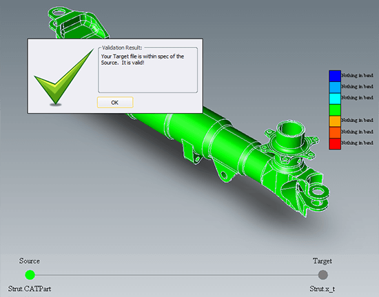
Figure 5 – CAD validation ensures that derived parts are within tolerance.
CAD Validation
Invalid CAD files can also become a bottleneck. Because of the different ways that model topologies are described and referenced in different CAD systems, when you translate from one format to the other, geometry may change. If the change is very slight, it may not matter; however, even a slight change could affect an assembly fit or the functioning of a related assembly which would constitute a significant production bottleneck. The potential for topology changes can be even more extreme when translating from or to STEP files, since the STEP format is easy to write a poor translator for.
Boeing D651991 – For these reasons, there are standards to guarantee that any derived models are within a specified tolerance to the original part geometry. Boeing’s D651991 spec is one example, implemented to guarantee that aerospace components perform as designed. CAD model validation analysis compares the original CAD model to the derived CAD model, and notes any variations outside of tolerance (for example, 0.005 in).
Where the derived model envelope is inside the original part envelope, the model is colored red, and areas where the derived model envelope is outside of the original model envelope, the part is colored blue. With a little practice, it becomes intuitive to read these heat maps. A report can be generated to show the results of the validation analysis, including any specific areas of concern.
The Cost of Invalid CAD Models – Without proper model validation analysis, it is possible that manufactured parts may not conform to acceptable tolerances, and Boeing or other customers may issue the supplier a Corrective Action Report or initiate similar corrective procedures. When the original model and the derived model are not within tolerance, downstream manufactured parts may not fit, and could even pose a safety hazard. Corrective actions initiated by the customer can be burdensome to the supplier, sometimes involving the supplier having to host, at their own expense, one or more on-site corrective action customer representatives, in order to guarantee that proper design, engineering and manufacturing processes are observed.
Quality Control
If quality control can be improved, fewer defect parts will take up the valuable time of bottleneck machines on the factory floor. In this scenario, think of bottleneck machines as machines that are bottlenecks to production.
One way to test product quality is by comparing Coordinate Measuring Machines (CMM) or other scanned part XYZ points against the authority CAD model. Point to Part Analysis works similarly to revision and validation analysis, creating a color-coded heat map to show which points are within or outside of a tolerance to the original CAD model.
How else can you improve quality? A few influencing factors include:
- Using the best possible CAD formats for each task so that CAD data quality is as high as possible, thus reducing problems due to translations. When you can use native CAD data, you have better access to CAD metadata which can be critical in design, engineering and production processes.
- Using the best possible CAD model translators to achieve the best possible CAD model data.
- When necessary, using CAD repair tools to convert low quality spline geometry to higher quality analytic geometry such as lines, arcs, cylinders and planes, which can be better understood by downstream CAD applications.
- Employing CAD Revision Analysis tools to know what changed between revisions.
- Taking advantage of CAD Validation Analysis tools to make sure that the model derived from the customer’s model is within acceptable tolerances.
References
2013 3D Interoperability Report – https://www.plm.automation.siemens.com/en_us/Images/Lifecycle-Insights-2013-Collaboration-Interoperability_tcm1023-210162.pdf
TransMagic
TransMagic has best-in-class tools to view, repair, translate and compare CAD geometry. For a quick solution to your specific needs, check out the TransMagic Product Wizard.