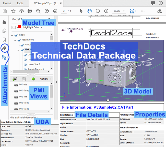
Figure 1 – A Technical Data Package can contain a lot of CAD data.
TransMagic’s Technical Data Package solution, TechDocs, gives you the power to deliver a single file to your customer or supplier which has everything they need in one place.
In Figure 1, you can see a 3D model which can be zoomed and rotated, automatically generated and attached CAD and polygonal formats, used-defined attachments, all PMI views and captures, User Defined Attributes, file details, mass properties, part details and assembly structure.
No more complicated sends to your internal and external customers; with TechDocs, all the key files are in one package, self-contained. TechDocs is available in TransMagic EXPERT.
TechDocs are summarized in the following video, or scroll down for more info:
TechDoc Settings and Publishing
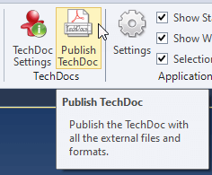
Figure 2 – Publishing a TechDoc is as easy as pressing the button, but check your TechDoc Settings to get the most out of TechDocs.
Publishing a TechDoc is as easy as pressing the Publish TechDoc button, which resides on the Home tool ribbon (see Figure 2). This will create a 3D PDF with PMI views, mass properties, surface area and User Defined Attributes (UDA) information.
But, to get the most out of TechDocs, check TechDoc Settings first to make sure the components of the TechDoc are as you want them. TechDoc Settings are divided into three categories:
- Title Page – the title page of your 3D PDF, with company address and logo.
- Part Information – UDA, mass properties, surface area, PMI views and captures, and PDF rendering options.
- Attachments – select the CAD & polygonal formats you want to have automatically created and attached to the 3D PDF, as well as user-defined attachments such as Excel spreadsheets, Word docs and other documents.
Title Page
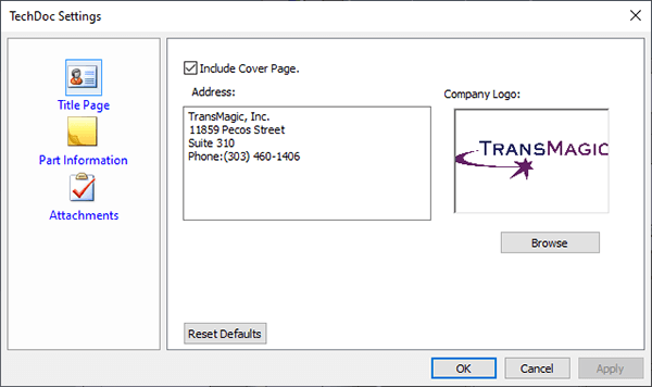
Figure 3 – the TechDocs Title Page dialog lets you input address and logo information.
The TechDocs Title Page interface shown in Figure 3 allows you to choose if you want a cover page or not, and lets you input the company address and logo.
To input your own company logo, click on Browser and select a BMP, JPG, PNG or GIF file.
Part Information
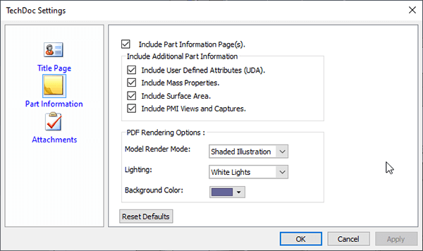
Figure 4 – The TechDocs Part Information dialog lets you decide what part information you want to appear in the 3D PDF, and how the model will be rendered.
The Part Information dialogue shown in Figure 4 lets you determine the type of information you want to go out with the document.
You can include User Defined Attributes (UDA), Mass Properties, Surface Area and PMI Views and Captures.
You can also choose the Model Render Mode (defaulted to Shaded Illustration), Lighting (defaulted to white lights) and Background Color (defaulted to white).
Note: Recommendations for background color and PMI color can be found at the end of this article.
Attachments
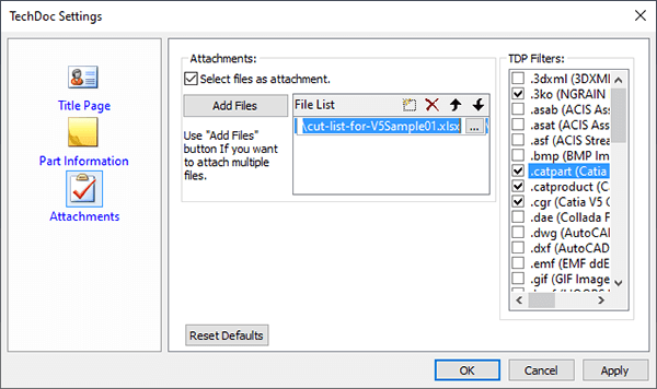
Figure 5 – Attachments allows you to attach CAD, polygonal or other types of documents to the TechDoc.
The Attachments dialogue let’s you choose which files (of almost any type) you want to attach the the 3D PDF.
In Figure 5, TDP Filters are shown at on the right; in this case, .3ko, .catpart, .catproduct and .cgr are selected. If you scroll down, there are other formats to choose from.
When you click Publish TechDoc, all selected formats will automatically be written and embedded into the 3D PDF. Note that only the formats which you have a license for will show up under TDP filters. This article was written using TransMagic EXPERT, which can write to native CAD formats such as CATIA. If you’re using the standard TransMagic eval, which is typically SUPERVIEW, you will only be able to write to polygonal formats.
If Select Files As Attachment is checked, you can click Add Files and choose any filetype. In this example, an Excel spreadsheet cut list is attached. Word docs, xml files and screenshots are other possibilities.
TechDoc Settings will remember your choices, so be careful to remove inappropriate documents from the File List when preparing TechDocs for different customers.
What TechDocs Look Like

Figure 6 – a sample cover page
TechDocs are 3D PDF files which can include the following elements:
- A 3D model of the part or assembly.
- PMI views and captures.
- The model or assembly tree, which can include semantic PMI, part names and assembly hierarchy.
- Part and material properties such as surface area, volume, material name, mass, density, center of mass, moments of inertia.
- File Details such as author, software version, units.
- UDA such as cage code, company, part number.
- CAD and polygonal formats automatically generated and attached at the time of publishing the TechDoc.
- Additional, user-defined attachments including Excel spreadsheets, Word docs, XML files and screenshots.
In Figure 6, you can see what the first page of a TechDoc looks like if you choose to include a cover sheet.
3D Content
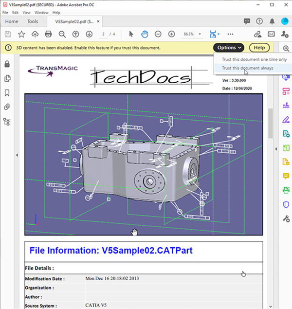
Figure 7 – Click ‘Trust This Document’ to enable 3D content.
Within a few seconds of opening the 3D PDF, you will be prompted to enable 3D content. When you click on ‘Trust this document’, you will get access to the 3D model shown in the viewing area.
Click in the screen area, and after a short delay, you will be able to rotate the model by pressing and dragging with your left mouse button.
If you right-click in the screen area, an Acrobat contextual menu will appear; from this menu, if you select Tools, you’ll be given the choice of Rotate, Pan, Zoom and Measure.
File Details
Also visible in Figure 7 is File Information such as the modification date, author, source system and version.
Model Tree
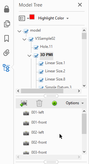
Figure 8 – The Model Tree contains part and assembly information and PMI views.
You can open up the Model Tree by clicking on the lowest button on the left side of the TechDoc. When you do, you will see the part or assembly model tree on the upper left, and a list of PMI views and captures (if they exist) in the lower left.
In Figure 8 you can see a closeup of the Model Tree. At the top of the figure is the model tree itself, where you can see the semantic PMI as well as any UDA. If this were an assembly, you’d also find the assembly hierarchy here, complete with subassemblies and parts.
Click the carrot symbols in the model tree in order to open up each section.
At the bottom of the figure you can see the PMI views and captures. 001-left is the first PMI view, which is taken from the original CATPart document in this case. Each PMI view only shows the PMI notes attached to that view, making it easier to digest and manage complex parts.
Click on any PMI view or capture to make that view current in the viewing area.
TechDocs and PMI
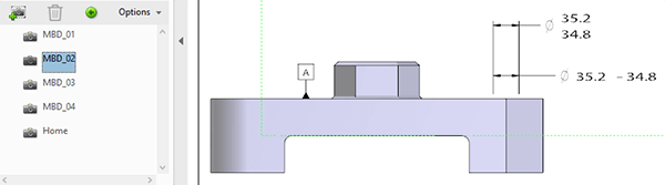
Figure 9 – PMI Views and captures can be activated by clicking on the view name.
To make a PMI View current, click on the view name. In this example, MDB_02 has been activated.
User Defined Attributes
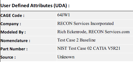
Figure 10 – User Defined Attributes include any CAD data defined in the original file by the company or author.
Part and Material properties are shown in Figure 10. Examples of UDA include CAGE Code, Company, Modeled by, Nomenclature, Part Number and Source.
Whereas mass properties and surface area are examples of CAD data you’d expect to see with every manufactured part, UDA is by definition flexible and can contain data as diverse as comments, codes to describe assembly, explanations of how true dimensions can change after assembly and assembly cut instructions.
Part & Material Properties
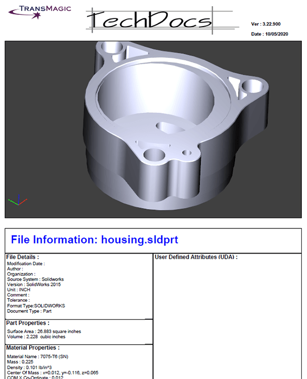
Figure 11 – Assemblies – all components are rendered and CAD data is displayed separately.
Assembly Example
For Part & Material Properties, an assembly example is shown in order to illustrate how assemblies are handled differently than parts in TechDocs. For assemblies, each component can be zoomed and rotated, and comes complete with part, material and UDA information (when available).
Part Properties
Part properties include surface area and volume (see Figure 11). The units used for this values are editable in TransMagic Settings.
Material Properties
Material properties include material name, mass, density, center of mass and moments of inertia.
Material will not show up here unless it has been applied either in the original CAD file, or in TransMagic. Materials can be applied to any part in TransMagic by right-clicking on the ‘material’ component of the part in the assembly browser, and selecting the desired material from the Material Properties dialog. See this example of how to apply materials to any given part.
PMI Color and TechDocs Background Color
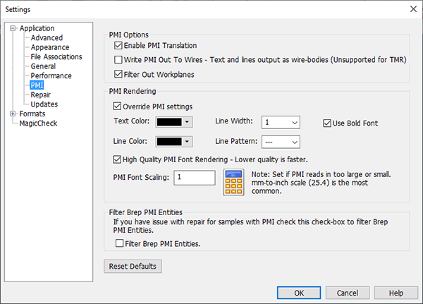
Figure 12 – Change PMI Text to black if you have a white or light background.
TransMagic recommends plenty of contrast between PMI text color and the TechDocs background color. If the TechDoc is going to be printed, white Background is best. This means you will want to change your PMI text color to black.
To do so, launch TransMagic Settings by clicking on the gear icon in the upper left corner of the TransMagic window. Then choose Application > PMI > PMI Rendering, and Override PMI settings so that Text and Line color are black.
Another option worthy of note on this dialog box is Enable PMI Translation (checked by default). If this is disabled, PMI will not be attached to files you open.