 Version 12.30.702 of TransMagic has added a new CAD format and nine updated CAD format versions, as well as some powerful feature enhancements.
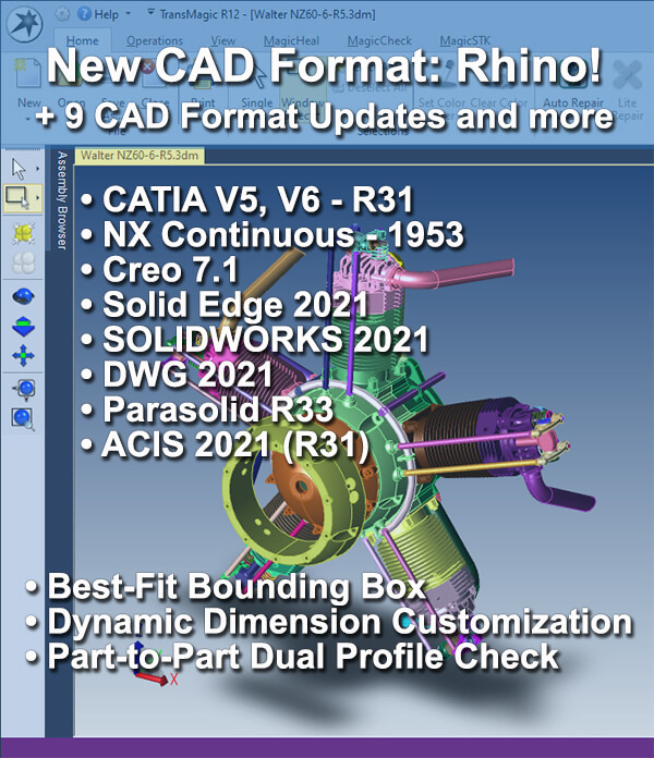
New CAD Format: Rhino! Supports versions 2 through 7 (read only).
Updated Format Versions to keep you up to date with your customers and suppliers:
- CATIA V5 2021 (R31)
- CATIA V6 2021x (R31)
- NX Continuous Release 1953
- Creo 7.1
- Solid Edge 2021
- SOLIDWORKS 2021 Write
- DWG 2021
- Parasolid R33
- ACIS 2021 (R31)
That’s not all in this packed point release:
Best Fit Bounding Box
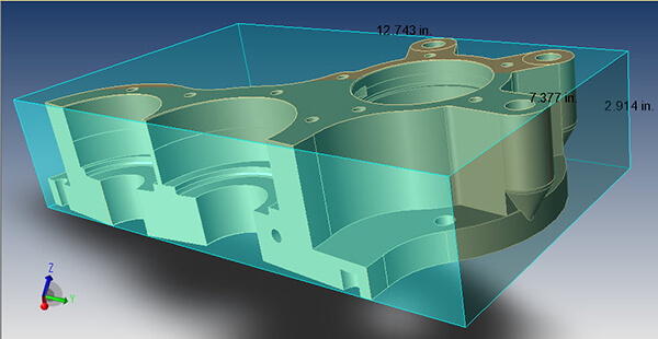
Figure 1 – The new Best Fit Bounding Box optimizes its orientation to best suit the geometry or orientation of the CAD model.
Best Fit Bounding Box, which allows the bounding box to shift orientations relative to the CAD model or assembly, to get the tightest possible fit and use of rectangular space. This improvement will help manufacturers to optimize packaging per part or product.
In Figure 1 you can see a CAD part at a unique orientation as compared to the XYZ coordinate system in the lower-left, but the Best Fit Bounding Box assumes the best-fit orientation in order to find the optimal bounding box fit. Note that the height, width and length of the bounding box is given in black text.
Bounding Box color and transparency gives you the ability to control the color and transparency of all bounding shapes (settings found under Settings > Application Performance).
Any bounding box, cylinder or sphere can be removed by simply selecting the geometry and clicking Delete on your keyboard.
Change Color, Line Width of Dynamic Dimensions
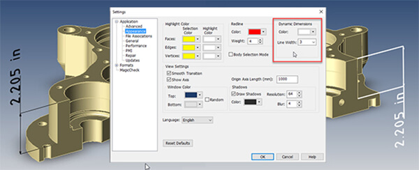
Figure 2 – You can now customize dimension line width and color.
Dynamic Dimensions can now be customized to any color, and to a line width of 1, 2 or 3 (3 is thickest). In Figure 2, at left, you can see the default dimension color and linewidth (of 1), and at right, the dimension color is set to white with the linewidth set to 3.
The new color and linewidth capability gives customers more flexibility in how their CAD data appears, and can make interpreting digital and printed dimensions easier.
Part-to-Part Dual-Profile Check
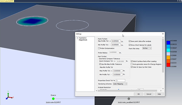
Figure 3 – The MagicCheck Plus and Minus Tolerance option gives you more flexibility with revision and validation analysis.
Part-to-Part Dual Profile Check means you can compare Min and Max Profile Tolerance independently. For example, you can specify a minimum ‘inside’ profile tolerance of 0.01 in, and a maximum ‘outside’ profile tolerance of 0.005 in. If cuts into the geometry violate the part envelope by .01 in or more, or if the geometry exceeds the outside tolerance by .005 or greater, MagicCheck will indicate those violations with the color heat map.
In Figure 3, there are two block models. The source model is a 2x2x1 box, and the revision it is being compared to is the same dimensions, but it has a .01″ boss, and a .01″ cut. Because the Max Profile Tolerance is set to .005, and the boss is larger than the tolerance, the boss is highlighted. On the other hand, the Min Profile Tolerance is .05″, too large to catch the .01″ cut, so that feature (on the right) is not highlighted.
Credit: Rhino assembly shown at top of page is a Walter NZ 60 radial engine, created by Peter Foks via GrabCAD.