Avoid Million-Dollar Manufacturing Disasters
Note: This blog post is a subset of a white paper entitled Avoiding Engineering Disasters which will be released soon, and contains more information as well as citations. We will post a link to the paper here soon.
In engineering, something as simple as declaring the wrong unit of measure can create a disaster costing millions of dollars. John Pike, space policy director at the Federation of American Scientists, stated, “It is very difficult for me to imagine how such a fundamental, basic discrepancy could have remained in the system for so long,” regarding the English to Metric units mistake at NASA.
Watch the video overview. Article continues below.
Engineering disasters can often be traced back to design errors that creep into downstream manufacturing processes through computer-aided design (CAD) software processes such as poor revision control or data compatibility issues. Even small mistakes might have big repercussions, valued in millions of dollars, from lost revenue, corrective work, time delays or investment loss.
Reviewing past engineering disasters provides critical information for avoiding expensive and high-profile mistakes by creating engineering processes that ensure accuracy throughout the design to production lifecycle. Author of To Engineer is Human, The Role of Failure in Successful Design, Henry Petroski states, “…the colossal disasters that do occur are ultimately failures of design, but the lessons learned from those disasters can do more to advance engineering knowledge than all the successful machines and structures in the world”.
NASA Genesis Probe
Cost of Mistake: + $260 million
The Genesis probe was sent to space to collect samples and solar wind data. On September 8, 2004, the Genesis probe crashed to earth, in Utah. The cause of the crash was that a pair of the probe’s accelerometers were installed backwards, preventing the probe from properly deploying its parachute for a landing. The estimated cost of the mistake is over $260 million.
The Hubble Telescope
Cost of Mistake: $1.5 billion
Shortly after launch, it was found that the images sent from the Hubble telescope were much lower quality than anticipated. The telescope’s mirror had been ground down 2 microns too thin. The result was sub-optimal light direction generating poor quality images. A repair crew was sent into space on December 2, 1993 to correct the issue using additional mirrors designed to compensate for the original mistake.
Mars Climate Orbiter
Cost of Mistake: $328 million
Launched December 11, 1998, the Mars Climate Orbiter’s intended mission was to collect data on the Martian climate. The Mars Climate Orbiter, which expected navigation data in metric units, was sent data in English units. The result was that the Mars Climate Orbiter ventured too far into the Martian atmosphere, where it subsequently overheated and disintegrated.
Airbus Wiring Harnesses
Cost of Mistake: $6 billion
A mismatch occurred with the Airbus 380 due to design software used at different Airbus factories not being compatible. The electronics harness designers in Hamburg, Germany, had an older version of CATIA, a 3D CAD Software, than the assembly plant in Toulouse, France. Although both had CAD software from the same company, data conversion between the mismatched software versions resulted in hundreds of miles of wiring harnesses that did not fit in the planes waiting in Toulouse. This resulted in a 2-year halt in production, and changes in upper management.
AVOID THESE FOUR THREATS
Learning from the past to create better processes today can not only avoid the more serious million-dollar mistakes but can also aid in maintaining production schedules, budgets and success rates while minimizing waste and lost revenue. Pulling from these case studies, Four Threats to Manufacturing On-Time and On-Budget are:
- Data Lost in Translation
- Excessive and Unchecked Changes
- Wrong Parts and Missed Deadlines
- After-the-Fact Errors
Threat 1: Data Lost in Translation
In addition to “neutral” CAD file formats, each computer aided technology (analysis, machining, simulation) includes its own list of proprietary data file formats. Surveys show that most large design issues are attributed to data exchange, and that design data exchange is commonplace with about 40% of users exchanging 100 or more files a month. Approximately 1 in 5 imported CAD models still contain errors that need to be manually fixed before they are usable, and nearly half of engineers polled say they spend at least half a day per week repairing design data. Data translation and geometry reworking creates potential for data loss and errors. Lost or inaccurate data were primary contributors to both the Mars Climate Orbiter and the Airbus disasters.
Threat 2: Excessive and Unchecked Changes
In the midst of enormous pressure to get products out on schedule, opportunities for error increase due to excessive and unchecked changes and data.
A significant percentage of CAD users experience excessive, unanticipated changes throughout the product development cycle, and dramatic or multiple last-minute changes to product definition. Changes in CAD system versions, and incompatibility were the root cause of problems with the Airbus 380, and for the Mars Climate Orbiter project, engineers failed to check mathematic units of measure. High-pressure, last-minute and unchecked changes could exponentially add to scrap material and time loss. In the worst-case scenario, unchecked changes and data results in project failure.
Threat 3: Wrong Parts and Missed Deadlines
While CAD files may be translated accurately and verified, additional product design information may still be lost. The process of understanding of the data can be delayed for weeks or months. Missing a CAD design change, or recording the wrong dimensional value can cause an entire project to miss delivery dates. While the Genesis Probe had the right parts, they were installed backwards, causing them to function incorrectly and destroy a project costing $260 million dollars.
Polls show that about a third of organizations miss project deadlines, and almost as many have ordered incorrect parts due to design data problems, poor tracking of design change orders and downstream impacts. The impact of imperfect design data flow affects the entire supply chain. The US Automotive industry estimated that $1 billion dollars was lost each year from CAD data interoperability.
Threat 4: After-the-Fact Errors
As in many situations, the sooner errors can be caught, the better the ultimate result. Catching errors and mistakes after the fact often results in higher ultimate costs from wasted materials, time and production capacity. One poll showed that in the automotive industry, erroneous CAD geometry was not discovered until part tooling had already been designed and cut in a significant proportion of the cases. Design mistakes, revisions and missed errors have downstream ripple-affects, with the ability to impact tooling, mold development, fixture design, machining, even assembly and packaging.
For the Hubble Telescope, the error in the mirror, ground two microns too thin, was not caught until the telescope was already orbiting Earth, resulting in a $1.5 billion dollar space repair The Solution: Accurate 3D CAD Design Comparison and Validation Software
Whether verifying two design revisions for changes, comparing the manufactured part to the CAD model or validating a clean file translation, checking and double-checking engineering designs is crucial. The ability to seamlessly communicate that information downstream and across the organization avoids the miscommunication and lack of information pitfalls in manufacturing. The solution is two-part: Design Validation and Information Communication.
To avoid million-dollar mistakes, the solution must possess the ability to compare, validate and verify 3D CAD data. The 3D CAD comparison process should be clear, accurate and easy, in order to maximize compliance and minimize wasted resources. With information communication being the second critical juncture, results should be easily sent downstream with the model.
Comparison software can provide visual evidence of changes to a model
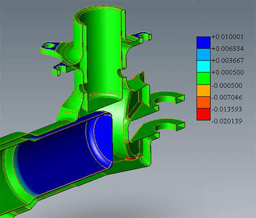
If the two models are overlaid, the differences are visually apparent, making a quick assessment possible; this is superior to having to look at two different screen images and guessing what has changed. Both models can also be shown separately if desired. Dynamically slicing the model through the X, Y and Z planes displays changes inside the geometry that might otherwise be overlooked or hidden from view.
With controllable tolerance variations, the software will highlight even the smallest change between 3D design files; any unintentional or accidental geometry changes in the design part will be numerically and graphically displayed. A visual color plot shows all changes such as if the holes moved or have new chamfers. Additional edits to model geometry introduced in the manufacturing processes will also be highlighted; validation of changes is an easy check with a CAD comparison solution.
Accurate CAD Comparison in 3 Easy Steps
- Open the parts you want to compare
- Click MagicCheck Settings to set the tolerance level for model deviations
- Click ‘Analyze Parts’ to show changes, revisions and deviations
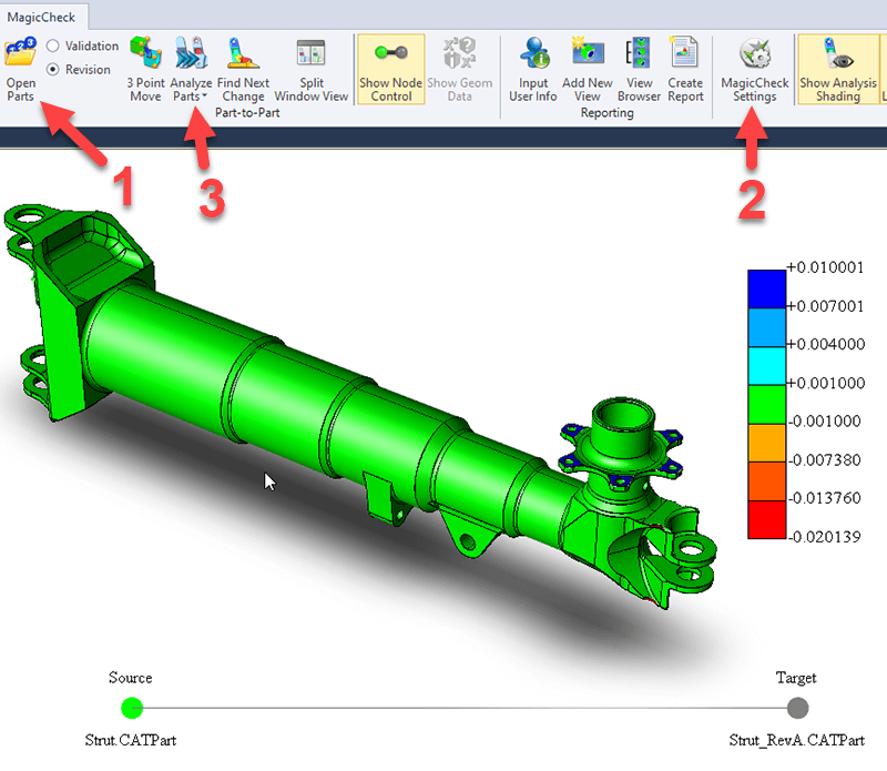
As can be seen in Figure 2, it’s easy to compare two CAD models; once the models are open, you simply set the allowable tolerance, and then click Analyze!
Of course there are nuances; the Revision button is selected in this screenshot. Revision analysis is for comparing CAD revisions; for example, comparing the last two models your customer sent you.
Validation analysis is for comparing the original CAD model given to you by the customer with the STEP or other CAD format you translated to. Validation analysis is something required by Boeing and some other aerospace firms, in order to guarantee that the geometry you’re working with is the same as the geometry they originally gave you.
Generating Reports
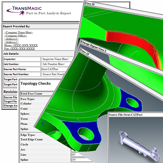
To aid in the flow of information between departments and suppliers, the ability to easily generate a comparison report is critical. A default report is shown in Figure 4. Report generation from the true CAD model inherently delivers higher accuracy results and less opportunity for human error. The report includes BREP model visualizations, accompanying model data and analysis specifications often required downstream.
With 3D CAD comparison software based on the actual geometric data, engineering designs and parts can be checked for file translation validity and design changes can be verified; manufactured parts can be validated to the original design and serve to catch any errors prior to production. Robust CAD checking and double-checking processes increase the fidelity of the design to manufacturing process. Using CAD comparison software can have an immensely positive effect on manufacturing schedules and budgets, knowing with certainty what changed, where it changed and how much it changed.
Using computing power to detect small or hidden areas of discrepancy surpasses the old and inefficient methods of manual visual inspection, removing the potential for human errors in inspection. Empowering users with the ability to find and solve issues quickly generates a competitive advantage, confidence in 3D CAD geometry, verification prior to production and, most importantly, reduces the risk of engineering mistakes and million dollar errors.
Try CAD Revision Analysis for Yourself
CAD Revision Analysis and CAD Validation Analysis are both part of the MagicCheck add-on, which is included with every evaluation version of TransMagic.