 CAD files are typically boundary rep files, or B-Rep files. They’re intelligent, in that they can be altered parametrically (in their native CAD system), they can be interrogated for mass, volume, surface area and edge length, they can have materials assigned, which will change their mass, and they can be measured and dimensioned.
Polygonal models are sometimes known as visual representations, or Viz-Rep models. They cannot be changed easily, and they cannot generate mass or surface values. Read more about the differences between B-Rep and Viz-Rep models.
So what do you do when, either from your customer or through some other circumstance, end up with a polygonal model?
You May Not Need a CAD Model Anyway
You may not need a CAD model. If your purpose is 3D printing or animation, a polygonal model is better anyway. The key thing is that for 3D printing the polygonal mesh should be watertight. If for some reason it is not, having access to the CAD model (if there is one) can be useful because you can use CAD model repair tools to heal any open surfaces, before converting again to a polygonal model.
There are also cases where STL files can be used for machining. Our article on Optimizing STL Output covers this as well as how to get your STL faceting just right for any given situation.
Ask for a B-Rep Model
If you need to do engineering, see if you can get a true CAD model from your internal or external customer. Sometimes it is a simple oversight that you were given a polygonal model in the first place; for example, JT files can contain both B-Rep CAD data and Vis-Rep polygonal data; it just depends on the JT Export settings in effect at the time the file was generated. In our experience, JT files only contain B-Rep data 40% of the time. Read more about how to open a JT file.
Dimensioning a Polygonal Model
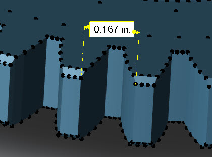 If you can’t get a true CAD model, you may be able to get by with what you have. A 3D PDF may already have some key dimensions or PMI on it. Or, you may be able to use TransMagic’s new ‘Polygonal Dimensioning’ tool to dimension lengths between nodes on the polygonal model. A screenshot of the process is shown at right. Using version 12.30.500 or later, open the polygonal model, making sure that you’re on version 12.30.500 or later, and click the Dynamic Dim button from the Operations panel. The nodes for all facet triangles will become visible. Then, simply press and drag between two nodes to create a linear dimension, and move the dimension text at will.
Read more about How to Dimension a Polygonal Model.
Converting a Polygonal Model to a CAD Model
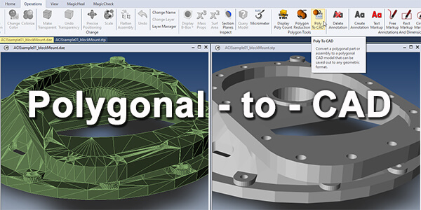 You can convert the polygonal model to a CAD Brep model by using TransMagic EXPERT; just be aware of size and complexity limitations. In one test we were able to convert a polygon assembly consisting of approximately one million polygons to a CAD B-Rep assembly, but it took a few hours on a laptop with 32 GB of ram, and the resulting STEP file was over 400 MB. So a million polygons is approaching a practical limit; it is often a good idea to reduce polygons before using a Polygon to CAD tool (polygon reduction is covered below).
In any case, a polygonal model when converted to a CAD model will retain whatever faceting was on the file at the time of conversion, as shown in the figure at right. Read more about Poly to CAD.
Optimizing the Polygon Model using Settings or Polygon Reduction
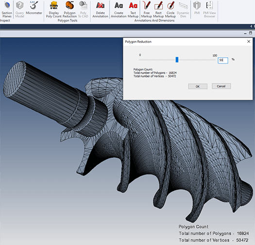 If you do need to reduce polygons prior to converting to CAD B-Rep, there are a few ways to do it. If your CAD or CAD translation system has the ability to save out to polygonal formats, there is usually a setting to define the density of the mesh. In TransMagic, for example, you can adjust the settings for saving to polygonal formats by defining the Normal Deviation, Maximum Surface Deviation, Maximum Edge Length and whether you’d prefer to use Procedural Faceting or Adaptive Faceting.
You can alternately opt for a polygon reduction tool such as the one shown in the figure at right, which allows you to drag a slider to determine polygon density. The benefit of the polygon reduction tool is that it allows you to determine polygon mesh density more intuitively, since you can see the resulting mesh in real-time, as you drag the slider.