v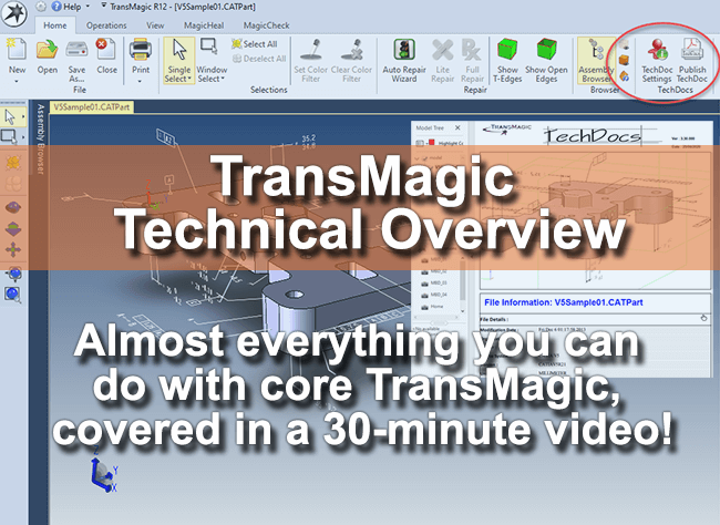 This article and video attempts to cover the majority of functionality you get with core TransMagic products, without going too long.
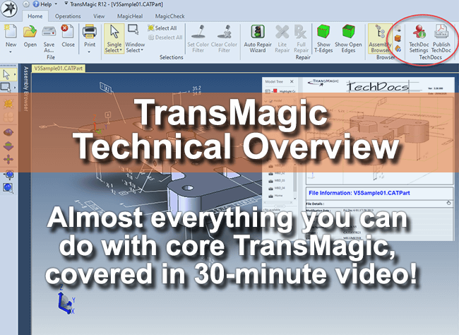
In a 30-minute video, you can see a quick overview of what is possible with core TransMagic in one sitting, without having to go to multiple pages or videos. Many of our customers use TransMagic only for translation and basic repair, but you may have more in your tool box than you suspected. This video gives you a glimpse of what is already in your toolbox. Please note Tech Docs is covered in this video and is available only in TransMagic EXPERT.
Other differences between core versions and functionality not covered in this video are outlined below.
Differences between SUPERVIEW, PRO and EXPERT
To sum it up briefly, all three core products will read all major 3D CAD formats as well as neutral formats such as Parasolid, ACIS, STEP and IGES.
The major differences are that:
- SUPERVIEW only writes to polygonal formats such as STL, 3D PDF, WebGL and Obj.
- PRO writes to polygonal formats plus neutral CAD formats including Parasolid, ACIS, STEP and IGES.
- EXPERT writes polygonal formats, neutral CAD formats plus native CAD formats such as CATIA, DWG, DXF, SOLIDWORKS (if you have a licensed copy of SOLIDWORKS on the same machine) and JT.
- See all supported formats on the CAD Formats page.
Other points of differentiation:
- With PRO and EXPERT, you gain access to the PowerPacks for SOLIDWORKS and Inventor, which give you additional formats you can read and write, as well as Lite Repair, right inside of SOLIDWORKS or Inventor. See an overview and video on the PowerPack SOLIDWORKS here, and see an overview and video on the PowerPack for Autodesk Inventor here.
- EXPERT comes with additional tools including Tech Docs (Technical Data Packages), Poly to CAD (convert polygonal geometry to true CAD Brep geometry), Group, Boolean and Split/Trim fuctionality (Group objects, perform boolean unions, split or trim geometry), Assembly Cuts (for weldments, currently available for Creo assemblies) and CAD Atomization and Data Extraction (Save entire assemblies out to parts in the format of your choice, save assembly, part, PMI and mass properties information to XML).
Not Covered in this Video
There are a few capabilities not covered in this video:
- Assembly Restructuring – although some parts of assembly restructuring are covered, such as Create Assembly and Flatten Assembly, other restructuring capabilities include renaming parts and breaking instances (so that you can access individual instance objects). See more on assembly restructuring here.
- Layer Control – you can select objects and assign them to layer numbers for more refined CAD visualization control. Simply select a part, click Change Layer from the Operations toolbar, and assign a layer number (such as 1). Then open the Layer Manager and select or deselect any given layer to control visibility of that layer.
- Precise Positioning – you can arrange components together into an assembly with planar and cylindrical constraints. Although this process does not use a constraint engine per se, it does place the components where you want them. An article on Precise Positioning will be forthcoming.
- Add-On functionality, including MagicHeal (advanced repair), MagicCheck (revision and validation analysis, as well as point-to-part analysis), MagicBatch (batch CAD translation and repair), COMMAND (enterprise, automatic translation and repair).