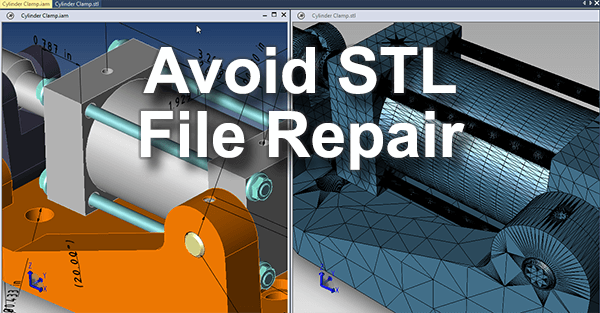
 While there are various ways to perform STL repair, it’s best to avoid it in the first place if you can. If you are starting with a CAD file, that’s where the diagnostic and repair process should start, before intelligent geometry is degraded into non-intelligent STL triangles. The further you get from the source information, the further you get from the original design. Just look at the data for yourself; CAD geometry is defined by cylinders, planes, arcs and lines, and can be measured precisely. STL geometry is just a congolmeration of triangles approximating the original CAD geometry. So by first making sure the CAD model is a quality watertight solid, you vastly improve your chances of quality, printable STL geometry.
Watch the video version of this blog post for a quick overview, or scroll down for more detail.
- Open Edges
- Intersecting and Overlapping Faces
- Reversed Face Normals
- Bad Edges
- Non-manifold Geometry
Open Edges
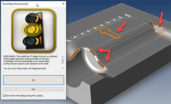
Figure 1 – Open Edges can be covered semi-automatically at the CAD level.
The most basic way you can avoid STL file repair is to make sure there are no open edges in your part. Open edges can be caused by missing faces or by gaps between faces. Some CAD systems and viewers have the capability of highlighting the open edges.
Note that the open edges are highlighted in orange. These open edges can then be patched quickly by first applying smooth or sharp edge attributes to the edges, and using Find and Cover approach. In this way, the model can be made watertight, and quality can remain high.
Intersecting and Overlapping Edges
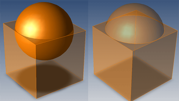
Figure 2 – Overlapping and intersecting faces need to be removed for 3D printing.
Here you can see a classic case of two intersecting bodies. It’s noteworthy that the only reason this intersection is visible is that we’ve made the cube element transparent.
Without the transparency, it’s difficult to know if intersecting or overlapping issues are present, unless the overlaps and intersects penetrate the outside surface of the part.
Sometimes the intersect or overlap can be solved by simply deleteing unnecessary geometry. In this case the intersection was easily resolved by running a Boolean union operation at the CAD level, so that there is a clear inside and outside to the part. Boolean unions are part of the advanced toolset found in both TransMagic EXPERT and the MagicHeal add-on.
Bad Edges
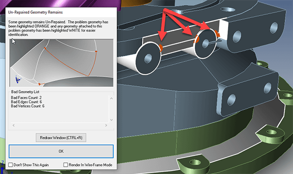
Figure 3 – Bad edges, vertices or faces can cause STL geometry to be invalid, and can be repaired at the CAD level.
Often, bad geometry (edges, vertices & faces) can be corrected by automatic CAD repair tools.
Here you can see bad geometry being detected; three bad vertices are found and colored in orange, and adjacent affected geometry is highlighted in white. But, one-button tools such as TransMagic’s Auto Repair Wizard can often repair bad edges, vertices and faces.
The diagnostic is useful not only for spotting exactly where the problem lies, but can help to reduce similar problems in the future by communicating the issue to the original designer.
Some bad edges can be repaired using Lite Repair, but if the problem is more serious, it can require Full Repair. Full Repair is available via the MagicHeal add-on.
Reversed-Face Normals
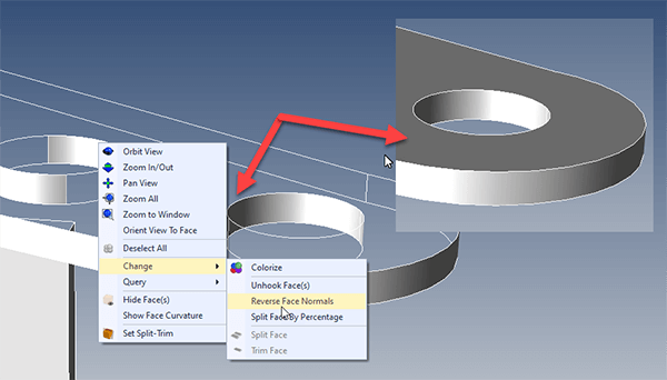
Figure 4 – Reversed Face Normals occur when one or more faces are flipped the wrong way.
In a watertight solid model, there is a definite inside and outside of the part. If one of the faces on the surface gets flipped the wrong direction, it can be referred to as an inverted face, or a reversed-face normal.
Normal refers to a theoretical line that is perpendicular to any given face or surface at any given point. For a cube, the normal line would point straight out from all six cube faces. If you see a model with what appears to be a missing face, it may just be that the face has a flipped normal.
To correct it at the CAD level, you have to select the face and then re-flip the normal. Then your CAD geometry will be correct, and you can proceed with converting the geometry to STL.
Non-Manifold Geometry
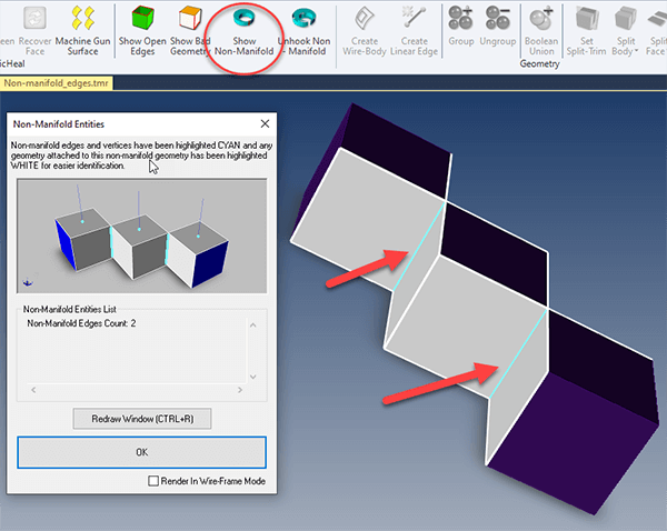
Figure 5 – Non-Manifold Geometry is when bodies which should be separated are seen as one.
Non-manifold geometry is geometry that could not exist in the physical world, and for this reason it could not be machined or 3D printed accurately. Here, three cube bodies are connected by infinitely thin edges. In reality, if this geometry was machined or 3D printed, it would come out as three bodies, not one.
Non-manifold geometry has to be corrected before it can be sent to the printer. In this case, you can use the Show Non-Manifold button to display the non-manifold conditions, and then use the Unhook Non-Manifold button to remove the non-manifold conditions. The result will be three bodies, not a single body with infinitely thin edges connecting it together.
Non-Manifold Geometry detection and repair is part of the MagicHeal add-on.
Where Bad Geometry Comes From
The reason this bad geometry cropped up in the first place could be because of poor modeling processes, or due to translation problems. If the model was translated from the native CAD format (such as CATIA, SOLIDWORKS or NX) to another format, fidelity can and probably will be lost.
This is especially true if the geometry is converted to IGES or STEP, because these neutral formats have more latitude in how they can be written, and the harm done to the original part fidelity is magnified if the IGES or STEP translator is not of high quality. When given the choice, it’s a good idea to keep the format native when possible, or translate to a geometric modeling kernel format such as Parasolid or ACIS.
Verifying that a CAD Model is Watertight
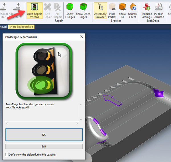
Figure 6 – It’s easy to verify that your geometry is watertight.
Making sure a CAD model is watertight is a process that only takes a few seconds. Simply open the file in TransMagic. If the file is a watertight solid, as the file opens, TransMagic will show you a green light.
If you want to run the Auto Repair Wizard manually, just click it at any time. A green light means the file is good, a yellow light means it has open edges, and a red light means there are more serious problems.
So, generating an STL file from TransMagic is a two – step process:
- Verify that the CAD model is watertight.
- Save the CAD file out as STL using system defaults.
STL Output Settings
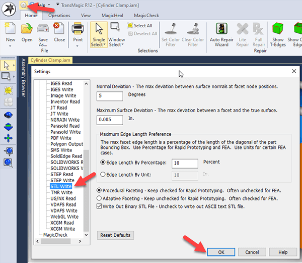
Figure 7 – STL Write settings allow you to tune the mesh density.
If your CAD file is watertight, you can just click Save As to write the STL file; but you may want to first adjust output parameters. STL mesh density can be adjusted factors such as Normal Deviation, Max Surface Deviation and Edge Length Percentage.
The idea is to have enough mesh density to so that curved geometry looks properly curved, without having an overly large STL file that takes longer to process. Depending on whether you are outputting the STL for 3D Printing or FEA, you may also need to adjust between faceting types.
Polygon Reduction
Figure 8 – Polygon Reduction gives you a slider to intuitively set polygon mesh density.
Another way to prepare STL mesh density is Polygon Reduction. Polygon Reduction sliders give you a more intuitive way to decrease polygons, so that you can see the final result before you accept it.
Once you click the OK on the Polygon Reduction dialogue box, you are prompted to convert the model from CAD to polygonal. At that point you can write the file out to STL.
Polygon Reduction is included in all core TransMagic products (SUPERVIEW, PRO and EXPERT). Read more about Polygon Reduction here.
Summary
Avoid STL File repair by making sure your CAD file is a good quality watertight solid model before converting it to STL.