 How did the British Cycling team go from only a single gold medal from in 84 years (1920 to 1996), to dominating Olympic cycling from 2008 to 2016, with a total of a total of 24 gold medals in three Olympics (8 in 2008, 8 in 2012, and 6 in 2016)? And how can exploiting marginal gains in cycling have anything to do with exploiting marginal gains in design and manufacturing?
Under the leadership of Sir Dave Brailsford, a former professional cyclist armed with an MBA and an interest in Kaizen (the Japanese concept of ‘continuous improvement’ in business practices), they looked for, found and exploited numerous opportunities to improve performance by 1%. Areas as logically important as aerodynamics and rider leg strength were studied and tweaked for tiny improvements, and other seemingly less important areas such as cleanliness and sleep consistency were also systematically addressed. Ultimately, the aggregate of incremental performance improvements in dozens of areas ultimately led to overwhelming superiority against the competition.
The Payoff
Not only did they win eight golds in 2008, but they also won eight golds in the 2012 Olympics, at a time when no other country could capture more than one gold in any bike event. They clocked seven world records and nine Olympic records. They also won the Tour De France for the first time in 2012, and over the next six years, won it five out of six times.
This kind of performance doesn’t happen by chance. What, specifically, did the lackluster British cycling team emerge out of obscurity to world domination?
Incremental Improvements
Some of the things Brailsford’s team did include:
- Sampling a wide range of massage gels to determine which one gave the best muscle recovery.
- Hiring a surgeon to teach the team the best way to wash their hands, in order to avoid colds and other infections.
- Handpicking mattresses and pillows for each athlete, and taking those same mattresses and pillows on the road for the Olympics as well as all 21 days of the Tour De France, replacing the default equipment in each rider’s hotel room with the optimized set to ensure a good night’s sleep.
- Carefully administering proper nutrition for all meals, particularly on the road via the team chef.
- The floor of the van used to transport the bikes was painted white so that dust and dirt could be more easily spotted and removed, thus ensuring that the team’s bikes were just that much cleaner and better running than those of the competition.
- Team members were evaluated for the power they were able to generate off the line and other performance criteria. Where the gap between current and desired performance was not too wide, team members were given exercises and training regimens to improve key stats, but where the gap was too wide, some team members had to be replaced.
- An important aspect to the process of continuous improvement was the solicitation of suggestions from the riders themselves, which allowed the riders a sense of buy-in and increased team motivation.
Dave’s team had three pillars that guided their approach; strategy, human performance / behavioral psychology and continuous improvement. The idea of marginal gains and a three-pillar approach can be applied to CAD Design & Manufacturing as well. If teams believe they have access to the best possible tools and training, and they are heard by management when they discover a new potential lever to improve performance, they will stay motivated.
Analyzing what it takes to win
The core strategy Brailsford’s team adopted was to analyze what it takes to win a cycling race and then work on those factors, from the kind of power-to-weight ratio a rider needs to complete the race to the racer’s ability to use aerodynamics and positioning tactics, and their ability to time and execute a winning sprint at the finish. As Brailsford says, “You have to know how to win before you start”.
Focusing on progression rather than perfection
Small gains have the power and value of being believable to the team, and it makes sense that they add up. Each time a cyclist engaged in a practice that was slightly better than previously, they felt they had achieved something, which created momentum, individually and for the team. Further, cyclists were encouraged to share their own ideas about what would improve them individually and as a team, and many of these ideas were adopted; so, they had buy-in. Brailsford fostered an environment in which the cyclists felt free to express their opinions in a constructive way.
Incremental improvements for aggregate gains
Continuous improvement is the aspect that most people take away from Brailsford’s success, but he’s clear that without the strategic understanding of what it takes to win at cycling, which involved considerable analysis, and the psychological health of the team and the individual athletes, he would not have had the same success. Every reasonable idea for improving the performance of the cycling team was considered, whether it meant improving health, strength, recovery rate, attitude, training programs, rest or sleep.
Continuous Improvement in Design and Manufacturing
If literally hundreds of aspects of cycling can be found in a relatively simple Olympic event, and the results led to dominance over every other cycling team in the world for three Olympics, how can you begin exploiting marginal gains in design and manufacturing?
Kaizen, one of Brailsford’s inspirational concepts, was actually born in Toyota manufacturing, so the idea of incremental improvements is not new to manufacturing. What may be novel about Dave B’s approach is the application to every possible angle of operations. To get the most out of their employees and machines, owners need to look at every nuance of both the design and manufacturing process, and engage their employees to suggest areas for improvement.
Areas for improvement
Where in your design and manufacturing processes might you find opportunities to improve performance, even slightly? Here are some areas to consider. Can you think of others?
Design for Manufacturing
Designing for Manufacturing (DFM) is the practice of designing parts and assemblies in such a way that they are easy and cost-effective to manufacture.
- DFM understands that any potential product problems are best solved at the design stage, while the design is still fluid and the costs have not multiplied. Every stage beyond design brings with it increased tooling and machine time expenses which should be minimized and eliminated where possible.
- Standardize fillet sizes and other part geometry for the tooling you already have, when possible, or at least according to standard inch or metric sizes. Use the same sized fillets where possible to keep the machinist from having to change tools too often.
- Don’t specify tolerances that are tighter than necessary, or tighter than the target machine is capable of. Too much precision is expensive and unnecessary.
- DFM seeks to use the most efficient material removal processes possible where machining is involved, and considers alternative processes such as stamping and Additive Manufacturing (AM) where suitable.
CAD/CAM Software
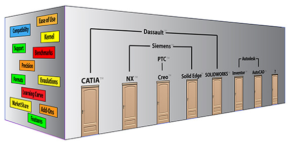 Do you have the best CAD/CAM software for the work you are doing, or is it time to reconsider the options? Some of the areas that Stephen Wolfe, an industry analyst, wrote about include:
- Capable, efficient 3D design
- Compatibility with customers and suppliers
- Drafting tools that meet your standards
- Reliability and stability
- Built in applications that help your business
- Pleasant business relationships
- Short learning curve
- Innovative R&D to protect your investment
- A dealer who can help you.
We’ve taken a fresh look at Wolfe’s list and added a few additional areas to consider in our series on How to Choose a CAD System.
CAD Applications and Productivity Tools
Do you have the right mix of CAD related applications to best design and manufacture your products? Are you using FEA tools to optimize for strength where it matters, size and weight? Does your team have easy access to tools to augment the CAD system’s default capability to perform translations, model repairs and comparisons between revisions?
Optimal Formats
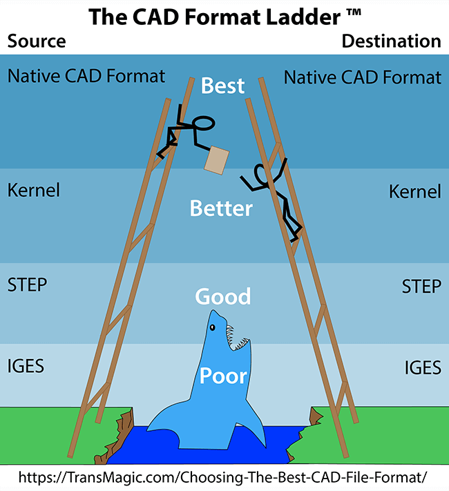 Are you using the best CAD format for each task? Do you keep try to use the native CAD format whenever possible, or do you, like many companies, default to STEP because everyone can read it and write it?
The formats you choose to translate from and to have a large bearing on the quality of your CAD geometry and data. Choosing the Best CAD File Format explains why the native format is always the best, the geometric modeling kernel is next, STEP comes in third place, and IGES should never or rarely be used at all.
Model Based Design
Are you taking advantage of Model Based Design (MBD) and Product and Manufacturing Information (PMI) to keep the CAD metadata with the CAD model, rather than working with models and drawings separately and risking them becoming out of sync, or risking misinterpretations of drawing information?
Feeds and Speeds
Have you maximized the speeds and feeds for the fastest each machine can safely run a given material? The tool, material, work holding and fixturing, chip removal and toolpath are all factors in managing feeds and speeds. Generally, you should be able to increase the speed (the RPM the machine tool is operating at) and the feed (the speed at which the material is being fed into the machine tool) until the material finish gets a little rough, then back the speed and/or feed down a notch until the material finish is satisfactory.
Suboptimal speeds and feeds can waste machine and operator time on the low end, or break tools on the high side. Poor surface finishes can also result if the speeds or feeds are too high. One machinist we spoke to says that he is able to take faster, lighter cuts with his Haas 2 mill, which results in faster turnaround for customers and less tool breakage overall.
Tool Breakage
Are there ways you could reduce tool breakage? Will a faster mill taking smaller cuts preserve tool life and still get your customer’s work done faster? Have you performed internal tests to see how you might be able to get more life out of your tools, or considered other tools which might out perform the ones you’re currently using?
NC Tool Paths
Are you constantly rethinking the best way to approach and cut that propeller blade, in order to save time and give the grinding team the best possible finish you can give them in the shortest amount of time? Would a different or new tool make a difference? Do you have a library of tool paths available so that new employees can easily ramp up to speed?
Production Engineering Video Library
Have you taken the time to document best practices for manufacturing? Is there a video library of how to create NC tool paths for different products, so you can easily ramp up new employees? A video library is a great way to share information, and minimize the time senior programmers or operators need to spend with newbies. Anything that can be documented, especially visually using video or photos, saves time later when new employees are trained, or when it’s time to review processes.
Raw Material Dimensions
Are the castings you’re getting from Spain costing too much time to remove material? Is it possible for the get castings that are closer to final product dimensions, in order to shave time off of machine operations? Would it be possible for the welding team to add material back to a propeller blade if a percentage of them have shallow cavities here and there, and would that mitigation cost less than what machining oversized castings is already costing? There is always a sweet spot when transforming materials to product; have you tried to find it?
Work Holding
Is your current work holding equipment easy and fast to set up? Have you stayed current on work holding options? Do machinists have any complaints with the current equipment, or suggestions for improvement? Do you keep work holding equipment well maintained and lubricated so it will perform well for a longer lifetime?
We spoke to a Gabriel Miller, work holding specialist at Elijah Tooling about this:
- “Work holding is an all-too-often overlooked aspect of outfitting machines for speed and precision. Most machinists say that their focus is on getting their tooling right or automating their processes, and while that IS extremely important to creating an efficient cycle, they miss the fact that the parts that they produce cannot surpass the quality of their workholding system. While chatter and poor surface finish often seem like a tooling related issue, it’s often their work holding that is causing these defects. Finding a work holding system that is simple, stable, robust and will repeat perfectly on every cycle is key to the entire machining process. Both cycle time and setup time are significantly affected by the workholding system, but a key to great efficiency it to create the most stable setup possible, which surprisingly, may not be a vise.”
- “Vises and clamps are usually seen as the only option when trying to hold/locate a part, but having an assortment of work holding options (tools in your bag, so to speak) that adapt to various applications will minimize waste and poor quality. Other options to be considered include: bolts, back-bolts, modular fixtures, vacuum plates, magnetic chucks, etc. Taking these options into consideration will lead to higher quality parts, but also greater capacity for complex, high value projects.”
- “Where possible, the use of picture-framing to hold/locate parts is highly desirable due to the ability to standardize the setup for many parts, as well as the supreme rigidity that can be obtained by its use.”
Stamping VS Cutting
 If there is large volume, stamping can be more cost effective than cutting. Stamping is fast, accurate, and the machines are simple to operate. On the negative side, if you’re working with low volumes, it might make sense to stick with cutting, since stamping requires tooling.
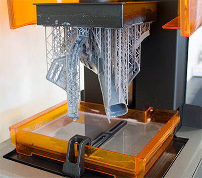
Additive Manufacturing for Jigs and Fixtures
Are you taking advantage of Additive Manufacturing (AM) to 3D print jigs and fixtures where suitable rather than making jigs and fixtures by machining processes? Though machined fixtures will generally be stronger, and have better accuracy and surface finish, 3D printed fixtures can be the answer if the fixture is difficult or expensive to machine. Have you considered bringing in AM equipment? Have you researched what particular equipment or materials would best serve your needs? When weighing the potential benefits, it’s important to calculate the post-processing requirements of any 3D printing process, in removing the support material and achieving the desired finish by cutting, grinding or sanding the printed part.
 Reducing the Number of Parts through AM and Casting
Any product that consists of multiple parts requires great care to be certain the parts will fit together with the proper tolerances and mates in order to function correctly. All parts in the assembly have to be engineered as separate parts, as an assembly, and inspected separately. Additive manufacturing makes it possible to 3D print the entire assembly as a single part, elegantly sidestepping the issues of tolerance and clearance between components. Another way to replace complex, expensive assemblies with a single part is through castings. This is a method Tesla is currently exploring, having purchased the world’s largest die-casting machine which will be used to manufacture the Model Y rear underbody which includes the guard rails. The Model Y rear underbody will be so accurate that it will not even require any CNC machining. There are no datums, tolerances, or any of the other engineering and machine-heavy operations to fuss with.
Generative Design
Would your product be lighter, faster or cheaper if you used generative design to optimize the shape based on the forces required? Generative design is the process of determining what areas of a component are fixed, such as the mounting points for a bracket, and inputting the forces which will be acting on the bracket, and then letting the computer algorithm iterate a series of shapes which will satisfy the solution with the least material possible.
Generative design gives the benefit of literally dozens or even hundreds of solutions in a fraction of the time a human engineer could do the work; in fact, some of the best solutions are completely non-intuitive, and would never be discovered by a human engineers, just because they are so unorthodox!
Benefits of generative design include:
- More design flexibility
- Decreased manufacturing costs, since some designs can require fewer parts
- Because the generative design process includes simulation, there is less uncertainty as to whether the part will perform well, thus there is less design and manufacturing rework.
- Reduced material means reduced weight, which can simultaneously decrease costs and improve performance.
Bottlenecks
Are there bottlenecks in the manufacturing process, for example a machine that is not as efficient as the other machines in the same production run? In the book The Goal, author Eliyahu Goldratt writes about a plant that was about to be shut down because of lackluster performance and missed production deadlines. The plant is ultimately saved through understanding the crux of the problem, which turns out to be bottlenecks in the production line. A machine and a heat-treating process are discovered to be the constraints which kept the plant from achieving their targets, which lead to overstock, dissatisfied customers and stressed-out employees. Discovering these sometimes-hidden constraints and eliminating them, or at least reducing them, can be the key to increasing manufacturing throughput.
Cleanliness & Order
Brailsford’s team found that painting the floor of the bike transport van white made it easier to spot dust and grime, and thus easier to keep clean to protect the precision bike equipment. Organized and tidy engineering and production areas can make it easier to find documents and tools. Tool shadow boards can make it easier for machine operators to find and replace tools. Strongly discouraging tool sharing between machine stations can keep tools from drifting to other stations. Especially during this season of Covid-19, making it easy for employees to distance, wear masks and keep their hands clean should payoff in decreased lost time.
Meetings
Know what the desired outcome of the meeting is, and structure the meeting towards that outcome. Prepare readable minutes for each meeting so each attendee can see what was discussed and decided at the previous meeting.
Where TransMagic can help
Ensuring the best possible CAD translation
Not all translators are created equal, and the quality of the CAD model you receive from your customer will depend on the quality of the translator that reads it. If you’re having any problems at all with customer CAD data, you owe it to yourself to try out world-class, licensed translation, as opposed to the default translators that come with your CAD package.
Sometimes a CAD viewer is all you need
If some staff are using full-blown CAD systems for viewing, quoting and estimating, you may be able to save in licensing fees, maintenance and training by moving to a simpler solution which is affordable, scalable and is intuitive enough for most people to use immediately.
Diagnostic Insights
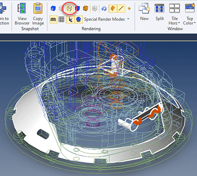 When there are problems, and automatic repair measures don’t work, it can sure help if you have a way to determine, visually, what’s wrong with the file. In the figure at right there is some problem geometry highlighted in orange, and adjacent areas are highlighted in white. The model is in wireframe display mode so that is easy to see inside and behind the model – yet at the same time, all problem geometry remains shaded so it can be easily seen.
TransMagic has several diagnostic tools like this, for telling you where open circuits are, whether the geometry is spline-based or analytic, how many tolerance edges there are and where non-manifold geometry exists.
Automatic Repair
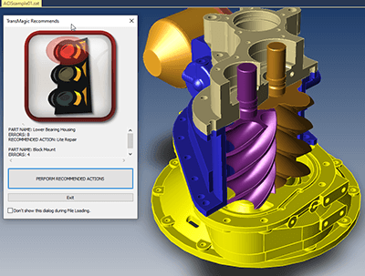 All core TransMagic products come equipped with Lite Repair, which checks the integrity of your CAD files as soon as you open them. If you get the green light, the model is good. If yellow, you’ve got a surface which it can quickly stitch into a watertight solid. If it can’t, it will highlight open circuits in the model so you can repair them with TransMagic’s advanced repair add-on, MagicHeal. MagicHeal includes Full Repair, another automatic repair tool which fixes more complex issues like inverted vertices. Both of these tools can fix a large percentage of your CAD geometry errors in just a few seconds. More advanced MagicHeal tools can generate faces from surrounding geometry.
Revision Comparison
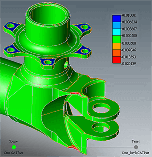 Do your customers ever send you part revisions with undocumented changes? Our industry contacts tell us that is actually the norm. Missing an undocumented customer change can drastically throw off the accuracy of your quote, as well as leading to the wrong part being machined or molded. Some engineers and designers check customer revisions by comparing them visually, but this technique will not be effective if the changes are small. To ensure that you know what has changed in a customer revision, use a tool built for that purpose. TransMagic MagicCheck will show you what has changed and how far out of tolerance it is, and even generate a report showing areas of concern.
Model Validation
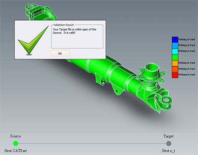 If you’re doing engineering or manufacturing for a major aerospace OEM, you will typically need to translate their CATIA or other format into SOLIDWORKS, STEP, or some other format to perform your processes. Boeing and other aerospace firms will ask you to validate that the models you are using for in-house engineering or manufacturing are within a tolerance of the files they initially supplied to you. CAD model validation is similar to revision comparison, but it is a pass/fail analysis. A report is generated showing areas of discrepancy.
Batch Translation
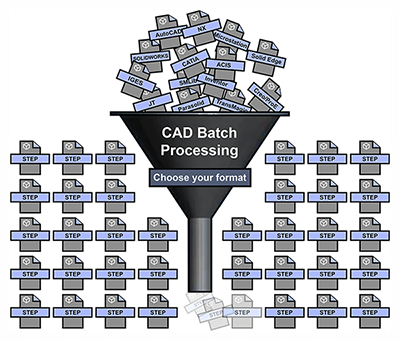 If you have a lot of CAD files to translate, it can be a tedious, time-consuming process. Find the file, open the file, wait sometimes 30 minutes for larger files to open, adjust translation settings if necessary, Save As to the format of your choice, and again wait for the process to complete. The process can tie up a machine, and in some cases a designer or engineer, for hours or even days at a time. Batch translation allows you to pre-select all the files you want to translate, adjust any settings, select the folder you want the translated files to be saved to, choose the format you want to convert to, and then you just click Go. As soon as you do, the batch process has begun, and it will not stop until all files are translated. Files can batch translated at lunch, at the end of the work day, or over the weekend, freeing up the machine and designer / engineer tasks that make better use of their skills.
Floating Licenses and Remote Use
 A TransMagic license can be floated among a team of users. A 2/10 installation gives ten people access to the license, but only two can run the software concurrently. Once either user closes TransMagic, it is checked back in. System administrators can check to see if a user is holding on to a license. There are many variations of floating licenses possible, for example 1/10, 3/10, 3/20, etc.
If, for example, you are going to be working remotely for a week, you can click Transfer Activation from the Help menu, and immediately your current machine installation will be de-activated. You can then use the same Activation ID on your laptop or other device and activate that until you are ready to move back to the other machine.