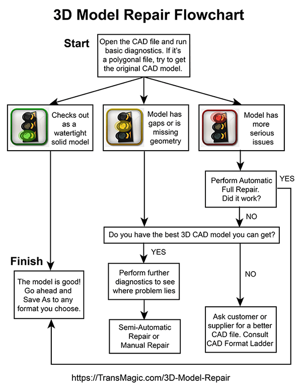
3D Model Repair Flowchart
3D model repair can cost companies an immense amount of time. Considering the costs to engineer and designer productivity, as well as the potential delays to critical projects, it is critical not to spend any more time or resources on repair than necessaary.
As indicated in the flowchart at right, the major steps would include:
- Start with the best, original CAD model when possible.
- Run basic diagnostics to determine if the file is good, and to discern what and where the problems might be.
- Your diagnostic software will usually break results into two or three categories; good, missing geometry, and corrupt geometry. At this point, you may want to run any automatic repair tools, but would want to forego more time-intensive repairs in favor of step 4.
- If the model or assembly has problems which cannot be easily resolved, check with your customer to see if you can get a better CAD model. Use the CAD Format Ladder to help in this process.
- If you can’t get a better CAD model, you’ll need to repair or rebuild the 3D model. Advanced diagnostics will help you determine exactly what you need to do.
- Repair or rebuild the geometry, either using semi-automatic repair tools, or manually, using your CAD system.
1. Start with the CAD model
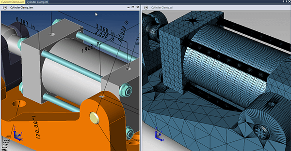
At left, CAD models are more precise, and polygonal models, at right, are only approximations.
3D model repair is best performed on the original model when possible – so if the damaged or corrupted model is polygonal (STL, OBJ or similar formats), see if you can get the CAD model that was used to generate the polygonal model. The original CAD model is closer to the original design and ‘truth’ than the derived polygonal file, contains more geometric information, and can often be more easily repaired. Polygonal files are non-intelligent triangles which only approximate the original CAD geometry.
Problems such as small gaps, open edges, intersecting edges, bad edges, reversed face normals and non-manifold geometry can often be solved faster more easily on the CAD side. For more in-depth coverage on this subject, see Avoid STL File Repair.
2. Perform Basic Diagnostics
Depending on the software and the settings, when you open a CAD file you will get automatic diagnostics.
Basic CAD model diagnostics can quickly determine if the model is watertight or not. Some diagnostic tools run as soon as the model is opened, and others need to be launched after the file is open.
TransMagic’s Auto Repair Wizard can work either way; by default, it initiates as soon as a model is opened in TransMagic, but this can be turned off in Settings. If you are opening a large CAD file, you may not want the Auto Repair Wizard to run, since it will add to the time it takes to open your file. You can turn this off in Settings > Repair > and disable Auto Repair Wizard During File Loading.
If your CAD system or viewing tool doesn’t give you access to basic model diagnostics, try running a mass properties calculation; a non-watertight model will not be able to return an enclosed volume or weight.
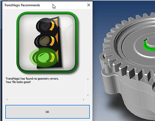
Green Light – Geometry is good
If the diagnostic tool (TransMagic’s Auto Repair Wizard in this case) tells you the model is a watertight solid, the file is good. You can proceed with whatever work you need to do, however, see the section on Query Model below. By running Lite Repair twice, you can convert spline geometry to analytic geometry for better downstream results.
Yellow Light – Missing geometry, large gaps, disjoint geometry
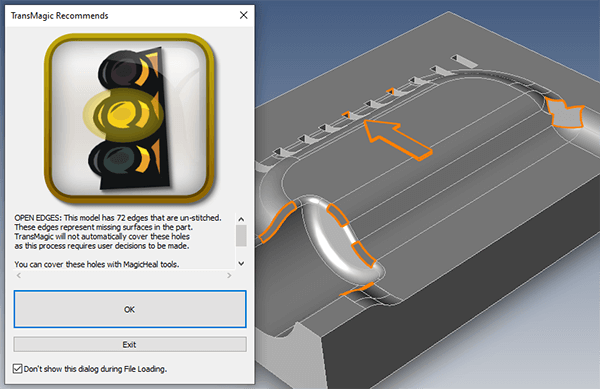
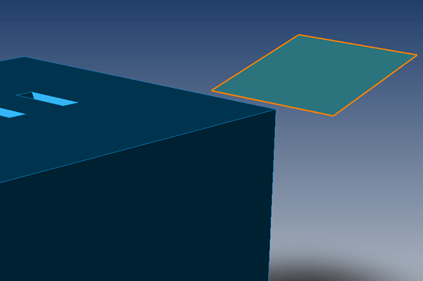
One of the problems which can trigger a yellow light is Open Edges, meaning that there are missing surfaces.
If the diagnostic tool tells you that the file you opened is composed of unstitched surfaces, has gaps between surfaces, or is missing faces, you’ll need to assess how much information is actually missing. Sometimes it’s just a matter of stitching the surfaces into a solid body, or closing the gaps if they are small enough; other times, you will need to replace the missing geometry.
In TransMagic’s Auto Repair Wizard, any time geometry is missing or there are gaps in the geometry, a yellow light is generated. You should get a visual indication of where the problematic geometry is, as well as a precise count. Openings are highlighted in orange so they can be easily distinguished. In TransMagic, you can alternately click on Show Open Edges at any time from the Operations toolbar to see this display.
In any case, if there is geometry missing, or the gaps are too big to heal automatically, you will require either semi-automatic or manual repair. MagicHeal, a TransMagic add-on, will allow you to select open circuit edges and assign smooth or sharp attributes, and then it will attempt to cover the open circuits for you. You can read more about MagicHeal’s advanced repair tools here.
However, before investing time and effort repairing a file with missing geometry, jump ahead to Step 4: Ask the customer for a better file, or attempt your file read with a better translator. Often times, the quality of the translator will determine who good and complete your CAD data is.
Disjoint Geometry and Duplicate Surfaces
A stray piece of construction geometry can trigger a Disjoint Geometry error.
One rule of thumb which can help simplify the 3D model repair process is to first remove or hide any unnecessary geometry. Disjoint geometry, such as the extra face shown at right, can also throw a ‘yellow light’ error. In this case, the face can be selected and deleted, and the problem will go away. Often, disjoint geometry is left over construction geometry. One way to separate out the disjoint geometry from the good geometry is to select all solid bodies using selection filtering tools (‘Select only Solid Bodies’ in TransMagic) and then hide that geometry; any remaining geometry will be non-solid disjoint faces or other construction geometry.
Sometimes you’ll find that there are actually two instances of the solid body in the same location – these are duplicate surfaces, and they need to be deleted before your model can be watertight. To see how to solve a similar problem with duplicate geometry, check out the post and video at this link.
Red Light – Bad or corrupt geometry
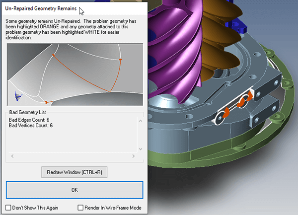
More serious problems such as bad vertices and bad edges can trigger a red light.
If the diagnostic tool indicates more serious problems such as bad vertices, bad edges, or self-intersections (a red light in TransMagic), you should get a count of how many bad vertices or edges were found, as well as a visual indication of where the bad geometry is located.
In the screenshot at right, the bad geometry is highlighted in orange, and the adjacent geometry is highlighted in white. Further down in this post, you can see a screenshot of the same part in wireframe mode, which causes only the good geometry to be displayed in wireframe mode, and the bad geometry remains shaded, making it easier to investigate problems which are inside the part.
In this case, a single button click to initiate Full Repair will resolve the problem.
3. If you’re going to Repair a 3D model, try Automatic Repair First
If you do have an automatic repair tool that can stitch surfaces into solids, remove unnecessary geometry, handle bad vertices, bad edges or self intersections, run it now. In TransMagic, Lite Repair stitches surfaces into watertight solids, heals small gaps between faces, and performs other minor repairs. All core TransMagic products come with Lite Repair.
For more serious problems there is Full Repair, which comes with an add-on called MagicHeal. Full Repair acts to correct bad vertices and edges, extend and re-intersect edge geometry to close gaps, and tweak surface geometry to restore lost tangencies. As discussed in step 2, a single button click can resolve some model issues. You can read more about Full Repair here.
If your advanced repair tool is not automatic and fast, you may want to consider step 4, in order to avoid spending too much time on repair if there is a faster and easier resolution.
4. Ask For a Better File or Try a Different Translator
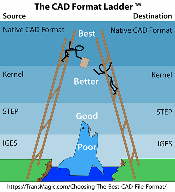
Choosing the best CAD format is easier using the CAD Format Ladder.
Some companies use basic diagnostics to flag problematic models, and before any more production time is wasted on these files, the customer or supplier is immediately contacted with a request that another file be sent so that work can proceed. At this point it’s a good idea to refer to Choosing the Best CAD File Format – this document recommends a hierarchy of CAD formats called the CAD Format Ladder, which will usually give the best results.
If the customer or supplier has sent you a STEP file, you may want to instead ask for the original CAD format – for example, CATIA or SOLIDWORKS (assuming you can read the native CAD format). This is because the original, native CAD file will have more accurate geometric information in it than the derived STEP file.
If you can’t get the native CAD file, you might be able to get the geometric modeling kernel format. The geometric modeling kernel is the mathematically precise model which the native file is built upon. For CATIA it is CGM, and for SOLIDWORKS and NX, it is Parasolid. To see a full list of the geometric modeling kernels for all CAD systems, see Which Geometric Modeling Kernel.
You can also try a different translator; not all translators are created equal, and if a better translator is free to evaluate, and saves you repair or even hassle time, it will be worth it.
It’s also possible that the customer or supplier has sent you a file that is flawed because of poor modeling practices, in which case it won’t matter what format they give it to you in.
5. Perform Advanced Diagnostics
If you’ve made it to this step in the 3D model repair process, you are dealing with either missing or corrupt geometry. Missing geometry is easier to assess (because it’s not there!), but for corrupt geometry, some insight into which exact geometry is corrupt would be helpful. To help identify corrupt geometry, you can:
- Display the corrupt geometry in the viewing area
- Show Non-Manifold geometry
- Check for Coincident Faces
- Access geometry integrity check results
- Query the model to see the underlying geometry of different edges and faces
- Assess tolerant edges.
A. Display the Corrupt Geometry
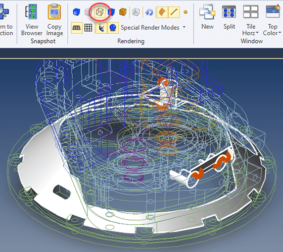
If you do have bad geometry, try switching to wireframe display which should cause only the bad and adjacent geometry to render, making it easier to see though and inside the part.
Some tools will allow you to see exactly where the issue lies. In TransMagic, if you have run the Auto Repair Wizard and want to see a visual of the problem, you can click Exit. This will cause the problematic geometry to be highlighted in yellow in the screen view, and adjacent geometry to be highlighted in white.
You can get a better insight into the problem by switching your rendering display mode to wireframe; this will switch all normal geometry to wireframe, but leave corrupt and adjacent geometry shaded. This allows you to ‘see inside’ the 3D model from different viewpoints to more easily pinpoint the problem.
Instead of clicking Exit on the Auto Repair Wizard, you can alternatively click on the Show Bad Geometry button from the MagicHeal toolbar.
B. Show Non-Manifold
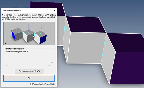
Show Non-Manifold will highlight any non-manifold geometry in cyan, and highlight adjacent geometry in white.
Manifold is a geometric topology term that means ‘To allow disjoint lumps to exist in a single logical body’. So, non-manifold means that ‘all disjoint lumps must be in their own logical body’. Depending on what you are doing, and which software you are using, non-manifold geometry can be a problem. Because of this, it’s important to be able to detect it, and repair it.
A non-manifold detection tool will show you where non-manifold conditions exist. In the screenshot at right, a single solid body has a three disjoint lumps. The three lumps are separated by two infinitely thin edges, and is not something you could machine or 3D print, because if you did, it would break into three parts. By clicking the Show Non-Manifold button in TransMagic, the non-manifold geometry is highlighted in cyan, and the adjacent geometry is highlighted in white. If you then wanted to break the three lumps into separate bodies, you could click on Unhook Non-Manifold.
You can read more about detecting and correcting non-manifold geometry here.
C. Coincident Faces
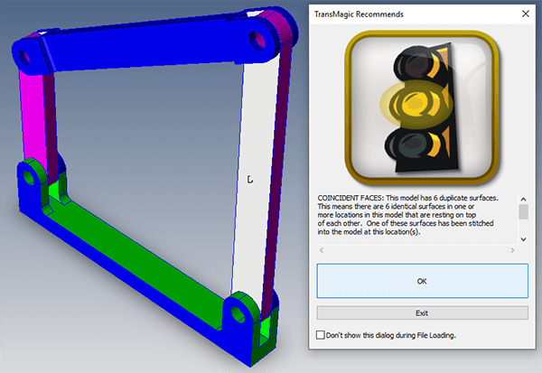
A Coincident Faces error can occur if faces neighboring surface bodies share the same plane.
If you get a Coincident Faces error, it means that two neighboring solid bodies have faces that are on the same plane. Since repair tools try to stitch bodies together based on edge proximity, when they run into two faces which are coincident and which do not meet at a logical seam, they get confused as to which face goes with the body being currently stitched.
If the solid bodies are already colored uniquely from one another, you can use Repair By Color to bypass any coincident faces. Simply turn on Repair by Color in TransMagic Settings, and run the Auto Repair Wizard (or select pertinent geometry and run Lite Repair). Once the surfaces have been stitched into separate solid bodies, turn off Repair By Color in Settings.
You can also sometimes get a Coincident Faces error if for some reason an extra copy of the model geometry exists in the same place as the original model. In this case, deleting the duplicate geometry should resolve the problem.
D. Access Geometry Integrity Check Results
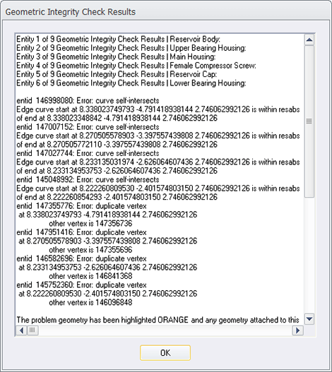
Geometry Integrity Check Results
If you want to go beyond the green, yellow and red lights to the data underneath, you can do so by going to the Repair section in Settings, and disabling Auto Repair Wizard During Repair and Geometry Checking, as well as Auto Repair Wizard During File Loading.
Then, the next time you run the Auto Repair Wizard from the Operations toolbar, you will get information about the integrity of each part in the assembly, the nature of the problem, such as curve self-intersections or duplicate vertices, XYZ locations and even specific affected entity ids.
If you run Lite or Full Repair while in this mode, you will get textual results such as:
- Lite Repair Result for: Reservoir Body
- Valid Solid Check:
- Passed valid solid check.
- Lite Repair Result for: Upper Bearing Housing
- Valid Solid Check:
- Passed valid solid check.
E. Query Model
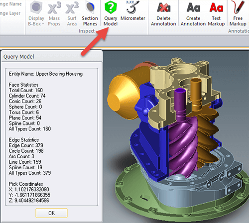
Query Model will display the analytic geometry and spline geometry for edges and faces on any selected part.
The Query Model button on the Operations toolbar will assess the geometry of any selected solid body.
Depending on the format and the quality of the solid body, some of the edges and faces will be splines, and some will be lines, arcs, cylinders, planes and other analytic geometry.
If Lite Repair is run twice on a solid body, or if Full Repair is run once, TransMagic will attempt to convert any straight edges to lines, flat geometry to planes, holes to cylinders, other appropriate geometry to conic or toroidal analytic geometry, and so on.
Analytic geometry can improve downstream CAD application recognition of geometry.
In the example at right, Lite Repair has been run once already. Depending on the history of the model, most if not all geometry is typically composed of splines.
F. Show Tolerant Edges
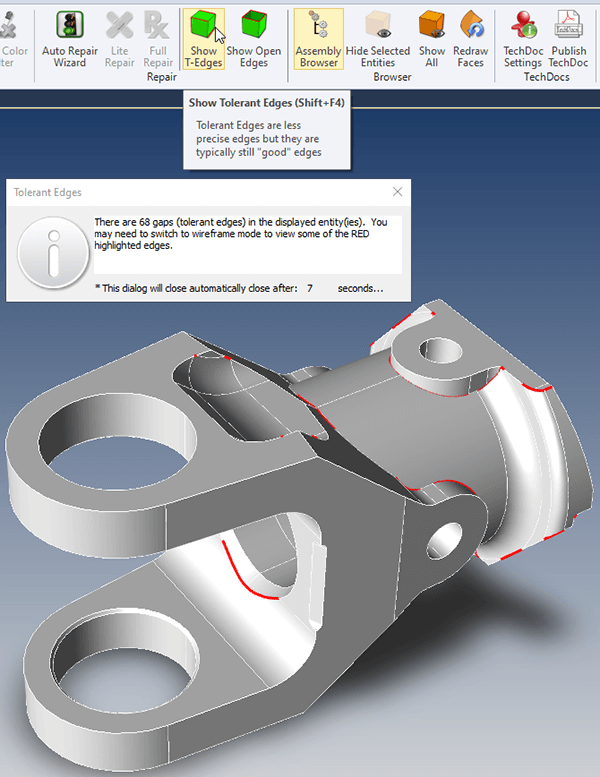
The Show Tolerant Edges button will highlight any T-Edges in orange.
Show T-Edges will highlight tolerant edges in red. Tolerant edges are a good measure of the accuracy of the model.
After running Full Repair, you will often see the number of tolerant edges go down, and sometimes reach zero. The absence of tolerant edges means that adjacent surface edges intersect precisely.
Tolerant edges indicate that there is a small but measurable variance between adjacent surface edges. Any geometry less than TransMagic’s precision, 0.000001 (10-6), is considered a tolerant edge.
Since not all CAD systems are accurate to that fidelity, tolerant edges are not unusual, and typically tolerant edges are nothing to worry about; if there are no other known issues, most of the time, your translation will be fine.
Fewer tolerant edges will generally mean better performance in downstream applications, and they serve as another data point when inspecting problematic 3D models. Read more about tolerant edges.
6. Manual or Semi-Automatic 3D Model Repair
Now that you’ve exhausted your options for a quick resolution, and you’ve gathered data on the 3D model, it’s time to either repair or recreate the model. In some cases this responsibility will fall on the customer or supplier. Your options are to:
- Ask the customer for another file
- Try another translator
- Replace missing or corrupt geometry semi-automatically
- Replace missing or corrupt geometry manually
In all four instances the next step would then be to go back to the top of the 3D Model Repair flowchart and run diagnosis again to see how good the repair or new file checks out.
A. Ask the Customer for Another File
This takes us back to step 4; don’t just ask for another file – see if you can get the native CAD file, or the geometric modeling kernel file.
B. Try another Translator
If you’re missing geometry, it may be that the CAD file you received was translated from the native format using a less effective translator.
C. Replace Missing or Corrupt Geometry Semi-Automatically
Replace missing or corrupt geometry with a semi-automatic tool such as TransMagic’s MagicHeal add-on. In cases where the surface exists, but is corrupt, MagicHeal allows you to simply replace the surface. In cases where the surface is missing, you can restore surfaces quickly by selecting a circuit edge, applying a ‘smooth’ or ‘sharp’ attribute, and then adding a new surface. An example of this process can be seen here.
D. Replace Missing or Corrupt Geometry Manually
Use your CAD system to rebuild the missing geometry, or remodel the part completely. This option is last because obviously it would be better to automatically, or semi-automatically resolve the problem.
View, Estimate, Repair, Translate…
TransMagic core products give you the power to view, estimate, measure, dimension, repair, translate, compare, automate and more. If you’re not already a TransMagic customer, there is a free TransMagic SUPERVIEW demo. To try the TransMagic Eval, CLICK HERE.
SUPERVIEW can write to polygonal formats. If you need the ability to write to CAD formats, consider TransMagic PRO; PRO enables you to write to neutral and kernel formats including STEP, IGES, Parasolid and ACIS. TransMagic EXPERT has the same write capability as PRO, but also includes native CAD formats such as CATIA .CATPart, AutoCAD .DWG and JT. Feel free to discuss your needs with one of our account reps.