TransMagic R14 has new CAD format versions and a wealth of new features. Here’s the rundown.
New Format Versions
- ACIS 2023
- NX 2206
- JT 10.8
- SOLIDWORKS 2023
- AutoCAD 2022
- Inventor 2023
- Solid Edge 2023
- Parasolid version 35
- 3D PDF up to 2023
New Features in All Products
- Assembly Explode
- Export BOM (Bill of Materials)
- Export Dimensions, Markup and Annotations to 3D PDF
- Show Origin
- Create Center Point
- Create Centerline
- Show Surface Normal and Vertex Normal
- Convert T-Edges to Edges
- Industrial Part Colors
New in MagicCheck: Compare PMI
New EXPERT and MagicHeal: Defeaturing
New Product: Magic STK – Bring your aerospace models into AGI’s System Tool Kit (STK)
How to Get R14
If you are an existing subscription customer, or a perpetual customer with maintenance, or an evaluator, you can install R14. Installation instructions can be found here.
R14 Video Overview
Assembly Explode
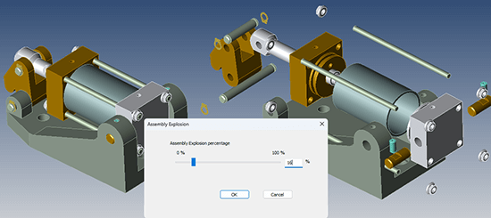 Assembly Explode prompts you to flatten the assembly, and then drag a slider to determine how far to explode the assembly components. The higher the percentage, the further the components will be from each other. Once you click OK, the parts will remain in their new location.
Export Dimensions, Annotations and Markup to 3D PDF
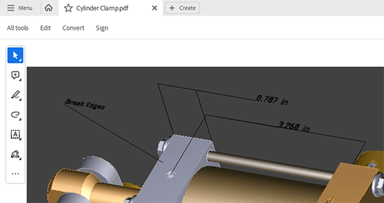 Dimensions, markup and annotations can now be imported into 3D PDF as edges.
Being able to bring these three types of CAD metadata into your 3D PDF gives you the capability of even more fully communicating with internal and external teams.
In the screenshot, you can see dimensions and annotations applied to the a part. Notice that there are no saved views, on the left. That leads to an important point – if you want to import markup, you should always do it in relation to a saved view. Also, the ability to write dimensions, markup and annotations is limited to Save As 3D PDF – you can’t achieve writing this CAD data to 3D PDF by using other pathways, such as Export Views to File from the View Browser.
Settings to write Annotations, Markups and Dimensions to 3D PDF
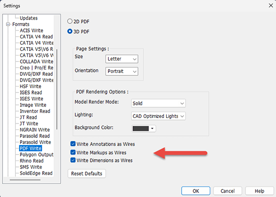 If you want to write Annotations, Markup and Dimensions to 3D PDF, make sure to check the appropriate boxes in the Settings > Formats > PDF Write dialog box. As you can see in the screenshot at right, Write Annotations as Wires is checked, as is Write Markup As Wires and Write Dimensions As Wires.
If you want to adjust the color of Annotations, Markup or Dimensions, look on the Settings > Appearance dialog box for Dynamic Dimensions: Color, and Annotations and Markups: Color.
Export BOM
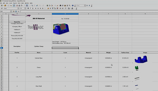 Export BOM (Bill of Material), found on the far right side of the Home toolbar under Special Functions > Export BOM, will output a Part Number, Part Name and Quantity detected in the assembly by default.
Note: In the next build of R14 (14.00.100) the plan is to put Export BOM in the Home toolbar to the right of Save As.
Optional attributes available in TransMagic Settings include:
- Part Image
- Material
- Weight
- Surface Area
- Bounding Box
- Address
- Logo
Industrial Part Colors
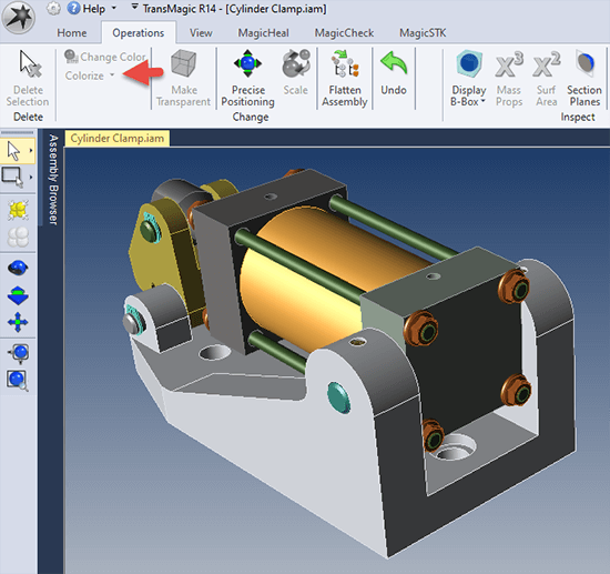 Previously, TransMagic applied completely random colors to models, assemblies and surfaces that did not have assigned colors. These random colors were sometimes hard to see against the default background, or difficult to see detail on (like black), or too similar to selected geometry (selected geometry is yellow), or simply looked bad.
In R14, we have implemented a Colorize button which will change all the selected parts to a random industrial color (typically the color of various metals), and if the model or assembly doesn’t already have assigned colors, ‘colorize’ will be automatically applied to the geometry upon opening the file.
There is a drop down for Colorize called Colorize With Random Color, which will apply completely random colors to all parts and surfaces.
Convert T-Edges to Edges
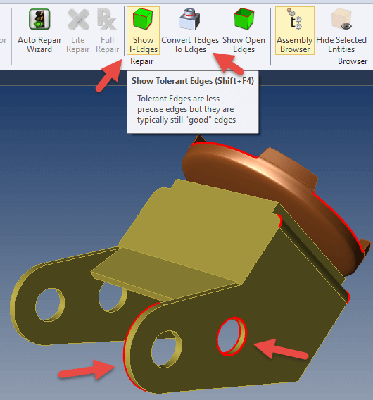 Tolerant Edges are edges on CAD models that are within acceptable range, but are less than the tolerance TransMagic is capable of (0.000001 inch). These edges come about in various ways, such as if the model was created in a CAD system that has a less precise tolerance, or though translation to other formats.
These edges can be seen by clicking on the Show T-Edges button. Though these edges can sometimes be at least partially removed by running Lite or Full Repair, if any are missed, you can simply convert the remaining T-Edges to Edges by clicking on Convert TEdges to Edges.
Removing T-Edges can be an effective way to improve the quality of the solid model, and paves the way for better results when you Save As to other CAD formats, and utilize those resulting models in downstream CAD-related applications.
I have personally solved repair issues which were unsolvable until I converted T-Edges to Edges, and recently our development team notified us that they were able to solve a difficult CATPart issue where the model could not be saved out to other formats until the T-Edges were converted to Edges. This is by no means a cure-all, but it is another tool in your tool belt.
Show Origin
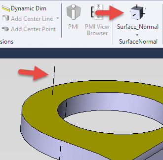
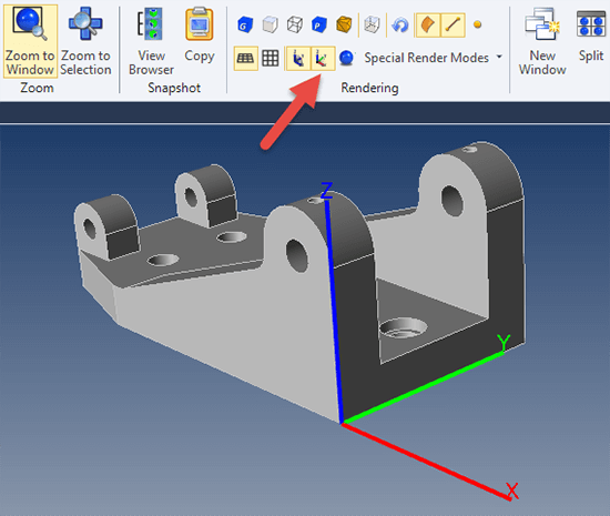 Show Origin can be found on the View toolbar under Rendering (see red arrow in screenshot).
Clicking on Show Origin will cause a red-green-blue axis to be drawn where the 0,0,0 origin of the part is located.
Show Origin can be useful in the process of moving the origin point to a corner or some other design feature on a part for downstream machining or measuring applications. See Add Center Point for more on this.
You can adjust the size of the origin axis in Settings under Application > Appearance > View Settings > Origin Axis Length (mm).
You can stop showing the origin by clicking on the Show Origin button again; so this button is an on-off toggle.
Add Center Point
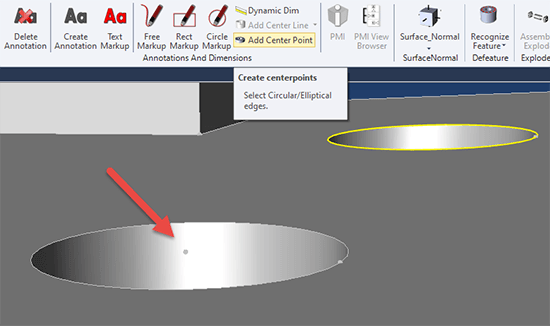 The Add Center Point button becomes active when you select a circular or arc edge. You can select edges using the Single Select tool set to Dynamic or Edge. Once you press the button, TransMagic will place a vertex at the center of the selected edge. However, you will not see the vertex unless your vertices are turned on. To turn on vertices, from the View toolbar > Rendering, click on Show Vertices.
In the screenshot above, one center point has already been added (indicated by the red arrow), and another circular edge has been selected, activating the Add Center Point button.
Add Center Point can be used with Show Origin and Precise Positioning > Move to Origin to move the center of any arc or circle of any model to the 0,0,0 origin for machining or coordinate measuring machine (CMM) purposes.
Surface Normals and Vertex Normals
 Surface normals indicate the positive direction of any selected surface. In the screenshot at right, the yellow face is selected, and then the Surface Normal button is clicked. This creates the black ‘normal’ line on the selected face, indicating the positive direction for that surface. Occassionally, you will run into geometry where one or more surfaces have inverted normals, and Surface Normal is one way confirm inverted normals.
You can also select any edge or group of edges, and use the drop down arrow under Surface Normal to create Vertex Normals at the vertices of any selected edges.
To make surface normals go away, just select the same geometry again, and click Surface Normal again; in that sense, the Surface Normal and Vertex Normal buttons are on/off toggles.
Add Center Line
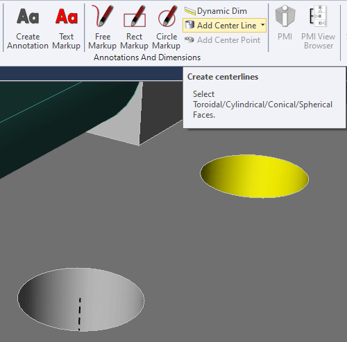 Add Centerline puts a centerline in any selected cylindrical face. In the screenshot at right, one centerline has already been added to one of the holes, and the cylindrical face of another hole has been selected. Any selected cylindrical face activates the Add Center Line button. Once the button is clicked, the center line will be added.
There is a drop down arrow next to Add Center Line, which makes the center line ‘Render On Top’ so that the center line will render on top of the surrounding geometry, in order to be more obvious. The ‘Render On Top’ will not actually occur until you click in the screen area again. To turn off ‘Render On Top’, just select a cylindrical face and click ‘Add Center Line’ again.
Note that if you Redraw the screen, the centerlines will lose their dashed line type. To get the dashed linetype back, just select a cylindrical face and choose Add Centerline again.
Centerlines can be deleted from the Assembly Browser.
New in MagicCheck
Compare PMI
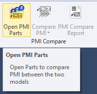 Compare PMI prompts you to open two part files that have PMI. Once the two parts are opened, you click on Compare PMI, which then returns a Pass if all the detected PMI in the Source part matches the detected PMI in the Target part.
You can then run a PMI Compare Report to see the specific PMI notes in each file.
New in EXPERT and MagicHeal
Recognize Feature
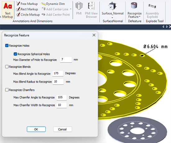 Features including holes, fillets and chamfers can be recognized and removed based on size and angles. Recognized features will have their faces highlighted in red.
The Recognize Feature button is located on the right side of the Operations toolbar (see screenshot).
In this example, we have dimensioned the small holes and determined that they are less than 7mm. We want to remove all the small holes, so we check both boxes for recognizing holes, and set the Max Diameter to recognize at 7mm.
The screenshot at right is actually an early implementation of this feature – in the mid-June 2023 version of this feature, the Recognize Feature dialog will have a Remove Feature button near the bottom.
New Product
MagicSTK
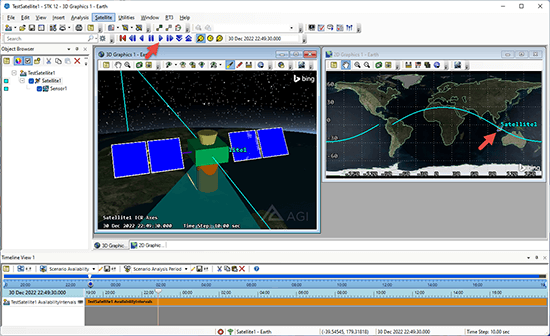 TransMagic’s new MagicSTK add-on gives you the tools to bring your CAD or polygonal aircraft, ground station, satellite or other spacecraft into Ansys & AGI’s System Tool Kit (STK) for industrial and military simulations with full editability.
You start with a CAD or polygonal model whatever it is you want to visualize in STK. Then you optimize the geometry into a suitable hierarchy, add select geometry to special groups; for example, articulation groups allow components to move in the STK simulation.
See a short video on TransMagic MagicSTK here.
Some of MagicSTK’s Features Include
 Easily open and validate CAD, Polygonal and Ancillary Documents
- Drag and drop components to create subassemblies and new hierarchies
- Create, position and designate Attach Points for cameras and other equipment
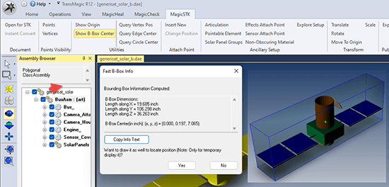
- Show Origin, Bounding Box, and Bounding Box Centers
- Query Vertices, Edge Centers, Circle Centers
- Ancillary Setup for Articulation, Pointable Elements, Solar Panel Groups, Effects, Sensors and Non-Obscuring Materials
- Explore Setup lets you see and control all Ancillary Document parameters easily
- Add Nodes to Ancillary Component Groups
- Scale, Transform and Rotate geometry at will
- Rename Components, Convert Multibody Parts to Assemblies
- Replace spaces with underscores per STK requirements