 Life before IGES and STEP
In the mid 1970s there were a handful of CAD vendors, often competing for the same business from large companies such as General Electric and Boeing. Some of the big vendors in those days were Applicon, CADAM, CATI (early CATIA), SDRC, Anvil, ComputerVision and Intergraph.
In those days, if Boeing for example was using CATI, and they needed to incorporate some subsystems designed by one of their suppliers (who were using another CAD system such as Applicon, for example), they had to write a translator specifically from Applicon to CATI. As you can imagine, the problem quickly became unmanagable as the number suppliers using different CAD systems increased. If there were some kind of CAD exchange standard, each CAD system would only need to translate to and from that single format.
The fascinating story of how IGES came to be
We’ve written elsewhere of how IGES was spawned, and it’s interesting enough that it at least part of it bears repeating here. The following is quoted from a National Institute of Standards (NIST) Special Publication.
In September 1979, frustration came to a head at the two-day Air Force Integrated Computer-Aided Manufaturing (ICAM) Industry Days meeting. On the first day, a representative from General Electric (GE) challenged a panel of CAD vendors, which included ComputerVision, Applicon, and Gerber, to work together to enable an exhange mechanism. While this need was intuitive from a user’s perspective, this was a very threatening proposition to the CAD vendors – who feared that sharing the structure of their databases publicly would be tantamount to giving away their competitive advantage.
It would have been easy to gloss over the challenge; after all, the major vendors all had at least token representation on the ANSI (American National Standards Institute) committee responsible for CAD standards. Instead, the ComputerVision representative responded with a challenge of his own: if Boeing and General Electric (and perhaps others) would contribute the CAD translators they had already developed, the vendors would share their database structures.
What led to this offer was just the right mix of business motivation and intrigue. Large Navy contracts were looming on the horizon, and no vendor wanted to look unresponsive to customer requirements.
In the evening after the panel, several interested parties gathered and asked themselves if a common transfer was really possible. The room had the right mix of people and ideas at the right time. This included an Air Force, Navy, and NASA representative, each willing to fund $25,000 for such an effort. A National Bureau of Standards representative, after a call to his boss at home for approval, was willing to champion it as chair and coordinator. The IGES Organization was formed by NBS in the spring of 1980.
How problems with IGES led to STEP
As the IGES team considered what the next version of IGES should include, they determined that there were some fundamental problems with IGES and that a new standard should be developed. Some of those problems were (again, from the same NIST special publication):
– Flavorings – IGES contained several ways to capture the same information, which made proper interpretation largely dependent on the particular “flavor” of the pre- and post-processors.
– File size/Processing time – IGES was criticized heavily for requiring large files that took hours or even days to parse with the average computing power available at the time.
– Loss of information during exchange – Information will inevitably be lost when information is passed between two CAD systems with inherently different capabilities.
– Lack of discipline, architecture – There was a perception that IGES was developed without rigorous technical discipline, and that formal information modeling would be useful.
– Upward compatibility – The need for generations of processors to parse files compliant with earlier versions of IGES thwarted the breadth and rate of change in succeeding versions.
– Automated a paper system – IGES was seen as a method to exchange engineering drawings, but not capable of capturing complete product data (including administrative information) to enable more sophisticated automation which would reduce or eliminated human intervention to translate.
– Subsetting – Vendors selected and implemented only portions of the whole of IGES, thus making exchange between two systems impossible without prior agreement on what was to be exchanged.
– Processor testing – There was no mechanism for testing processors or resolving errors between two processors.
There was a real, long term problem with IGES that would be difficult to fix: IGES communicated the lines and symbols appearing on an engineering drawing… but it failed to communicate the meaning of the information the engineering drawing was created to convey. The… study revealed that product features must be transmitted with the geometry so that computer -based applications could “understand” the engineering drawing. For example, an application looking at an IGES representation would see merely a circle on a part. The desired result was to be able to distinguish whether that circle was a surface mark or a hole.
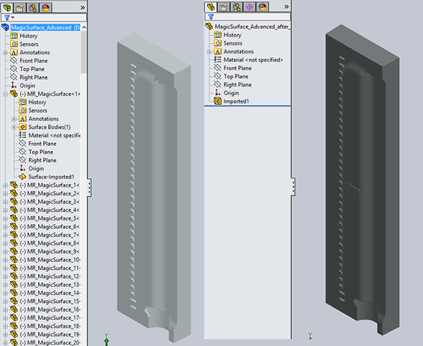
How unstitched surfaces look in SOLIDWORKS (left) vs the simplicity of a solid model (right).
From a 2020 perspective, some other shortcomings of IGES are clear:
- IGES is old – IGES began in 1980 and the last official version of IGES (5.3) was released in 1996. Some work was done on IGES 6 between 1998 and 2001 but it was never completed. By comparison, STEP is still being revised to this day.
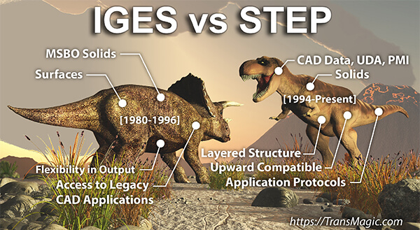
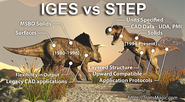
- IGES geometry is not as ‘information rich’ as solid geometry – The vast majority of IGES files are surface models, which have no mass properties or volume, and are difficult to dimension. They also do not support CAD data such as Model Based Definition (MBD) and Product and Manufacturing Information (PMI) data, which allow dimensions, notes and Geometric Dimensioning and Tolerancing (GD&T) information to be associated directly with the 3D model, rather than being siloed in a separte 2D drawing.
- IGES files are difficult to edit and often need repair – Ever try to edit a surface? Once you’ve been spoiled by editing solid models, going back to surfaces is difficult. Surfaces are non-intelligent in that they do not know about their neighboring surfaces, and gaps can often develop between surfaces during translation processes. In the figure above left, an unstitched model comes into SOLIDWORKS (and other CAD systems) and dozens, hundreds or even thousands of separate surfaces. Above right, you can see how the same geometry appears when it comes in as a solid part – much easier to understand and edit.
- Downstream applications prefer solid models – This would include Machining, FEA, 3D Printing, and even other CAD systems.
Why STEP is better than IGES
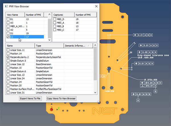
STEP AP242 can carry PMI, shown here in TransMagic’s PMI Viewer.
STEP was released in 1994 by the International Organization for Standardization (ISO). STEP stands for Standard for the Exchange of Product model data, but it is formally known as ISO 10303. Unlike IGES, which ended development in 1996, STEP development continues to this day; the latest version of STEP is AP 242.
STEP addressed each of the IGES shortcomings in turn:
- Flavorings were eliminated.
- Performance – I was not able to confirm any written evidence of improved processing time with STEP, though I was able to write to STEP in about 65% of the time needed to write to IGES in a 60 MB test assembly.
- Loss of information between CAD systems has been addressed though there may still be some areas for improvement. Where the input file conforms to the STEP standard, the data will be translated.
- Lack of discipline / architecture was addressed through the use of EXPRESS for data modeling and Context Driven Integrated Models (CDIMs) which led to better implementation of Application Protocols (APs) for addressing different industry challenges.
- Upward compatibility is considered a primary goal of STEP, which will have to be balanced with the reality that the standard does need to evolve over time. STEP has so far been, and intends to remain ‘upward compatible’ so that twenty years from now (in 2040), a modern STEP translator for say, CATIA, could read a STEP file created in 1995. Upward compatiblility is important because the functional life of some plane and ship designs can last 40 years or more. It is also true that when design teams are working out new iterations of products, they often rely on previous design files to build off of. Using STEP as an archiving format is key to this strategy.
- Capturing Product Data – STEP goes far beyond an ‘automated paper system’ by capturing product data such as User Defined Attributes (UDA) and Product and Manufacturing Information (PMI). The figure above shows a NIST STEP part being viewed in TransMagic’s PMI View Browser, which allows you to inspect PMI on a per-view basis, and save it out to 3D PDF.
- Subsetting – STEP lends itself less to subsetting than IGES did, though it is still possible for those writing STEP translators to take the easy way out by converting all entities to splines instead of cleaner, more robust analytic geometry.
- Testing – Conformance and interoperability testing tools were developed and utilized for STEP which included a testing harness, a test purpose generator, a coverage analyzer, a verdict criteria generator, a step file checker, an ARM/AIM browser and editor, a geometry analyzer and a NIST Expresso tool for validating information models and data sets.
Other advances the authors built into STEP
- Solids vs Surfaces – STEP files consist of solid geometry, as opposed to IGES surfaces. Solids are far easier to work with in CAD systems because the different faces know about each other and work as a unit, making the units easier to manipulate, edit and mate.
- Layered Structure – STEP has a layered structure which allows more flexibility as the data model grows.
- Modular – STEP is modular in that it uses Application Protocols (APs). APs make it possible to define and extend various industry requirements, and to ensure these requirements are fulfilled and can be tested. APs also make it possible to scope an industrial domain’s needs and document that industy’s terminology. Some of the many APs are AP 214 (Automotive Design), AP 218 (Ship Structures) and AP 223 (Cast Parts).
Where Does IGES Still Make Sense?
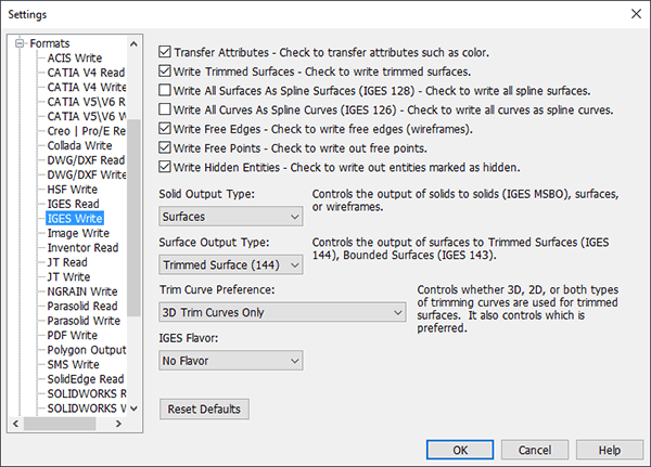
IGES Write Settings can give you the flexibility to write out to surfaces, wireframes and MSBO solids.
Normally, the only time IGES will beat STEP is when you’re working with an old CAD application which cannot read anything else, or in cases where the CAD vendor has placed a premium on the STEP translator and the customer has opted not to buy it. In these cases IGES may be the only option.
IGES is also a very flexible format. IGES Read has a wide range of options in terms of trimming curve preferences, IGES flavors, reading Manifold Solid Boundary Objects (MSBO – IGES’ implementation of solids). IGES Write (see figure at right) can write to MSBO solids, surfaces and wireframes, trim curve preferences and IGES flavors. As a side note, though some IGES translators do support solids, they are typically rarely used. In the days when I used to support customers with problematic CAD files, I was occassionally able to recover a corrupt file by resorting to IGES and making use of the many settings.
What’s even better than STEP?
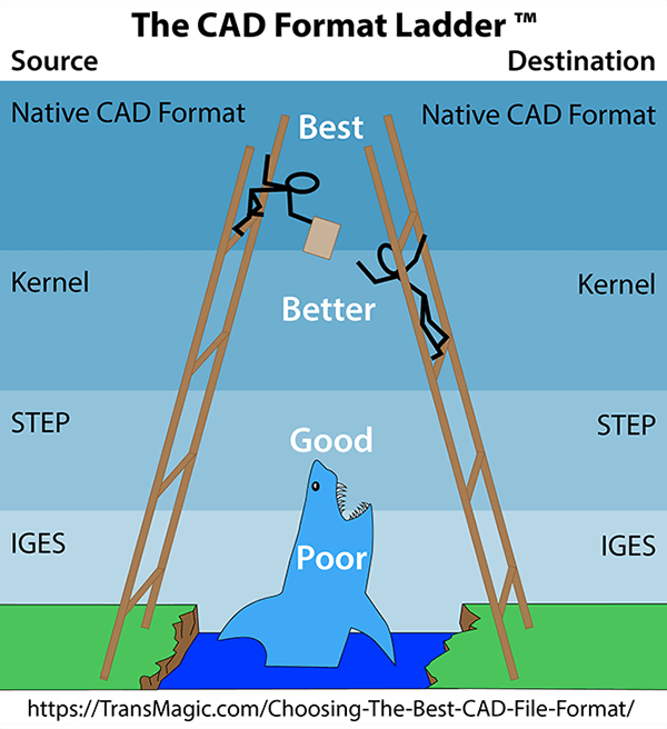
When you have the option, choose the native file first, the geometric modeling kernel second, and STEP third.
When considering IGES vs STEP, STEP is still the best, most dependable CAD format which every modern CAD system can read and write (though you may have to pay the CAD vendor extra for the STEP module). It’s really hard to overestimate the flexibility and power that the STEP format has given, and continues to give the CAD world.
However, in terms of geometric model fidelity, STEP will never be as good as the native format, nor will it ever match up to the geometric modeling kernel format which underlies each native CAD file. For this reason, TransMagic recommends a CAD format hierarchy of sorts, called the CAD Format Ladder. You can read more about the CAD Format Ladder here. Also see our listing for which CAD system uses which geometric modeling kernel.
Try TransMagic
If your struggling to read that CATIA or NX file, or you need to be able to write to a CAD format, and you want the best translator you can get your hands on, consider TransMagic. The formats TransMagic can read and write are shown on our CAD Formats page.
There is a free eval which will read all major 3D CAD formats, but if you need to be able to write to CAD formats, you’ll need to ask for an eval of either PRO or EXPERT. Get the Free Eval here.
Related Articles
In another post, we discuss 3 alternatives to IGES.
Our recent IGES post goes into the history of IGES as a ground-breaking universal CAD format, and a wider range of issues that eventually resulted in the STEP format.
Check out Six Reasons to Avoid IGES Files.