What can a CATIA viewer do?
Overview
- View ANY CATIA Format
- Zoom, Pan, Orbit, Save Named Views
- View PMI and Export to 3D PDF
- Change Color, Transparency, Cut Sections
- Measure, Dimension, Estimate
- Mass Properties, Surface Area, Bounding Box
- Optimize Settings for .Model, .CATPart and .CATProduct Read
- Optimize Polygon and Write to Polygonal Formats
Watch the Video – More Detail Below.
Open ANY CATIA Format
- CATIA V4 .Model parts and assemblies
- CATIA V5 & V6 CATPart and CATProduct parts and assemblies
- CGR Visrep models
- xCGM geometric modeling kernel files
- Detect Hybrid Brep / Visrep assemblies
Viewing Capabilities
Orbit, Zoom, Pan
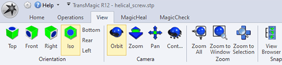
View, Rotate, Zoom and Pan CATIA Parts and Assemblies. Select orthographic views, Orbit, Zoom, Pan, Zoom Window and save named views to the View Browser to recall exact orientation, zoom and visual display settings at time oViewsave.
View PMI
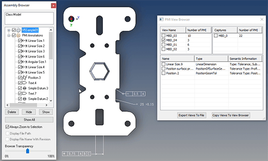
View and manage PMI. PMI visible graphically, in Assembly Browser, and in PMI View Browser, which allows you to selectively view PMI on a per-view basis, making complex PMI situations clearer and more digestible.
The PMI View Browser gives you the ability to view PMI section views (if they exist in the original file). Being able to see PMI sections was implemented on behalf of a major automotive manufacturer who wished to avoid hundreds of section drawings which were sometimes out of sync with model data. The PMI View Browser also gives you the option to export all PMI data to 3D PDF.
Write to 3D PDF
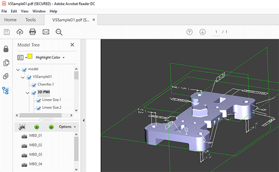
3D PDFs convey essential visual, assembly and PMI information in the 3D PDF format, which is readable by anyone on internal and external teams who has access to Adobe Acrobat; no CAD viewer necessary! 3D PDF allows anyone to zoom, rotate, pan and access all saved PMI views by clicking on the list in the left side of Figure 3.
If team members need the ability to access true Brep CAD data, TransMagic SUPERVIEW will allow them to do so – but often stakeholders only need to see the 3D PDF version.
Change Color, Make Transparent, Section
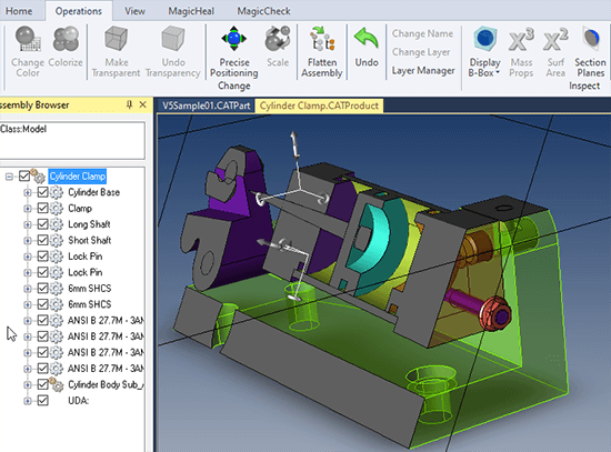
Change part, face or assembly colors by selecting the part and choosing your color; select and add transparency to parts or assemblies.
Sections can be cut through any angle, along X, Y or Z axes. Rotate each Section Plane as desired. Sections can be turned on and off by clicking on the Section Planes X, Y and Z buttons.
Also shown in this screenshot, a Layer Manager allows you to select key geometry and assign it to layers; geometry can then be made visible or invisible on a per-layer basis. Alternately, you can Hide or Show any selected geometry as needed.
Measure & Interrogate
Dimension and Micrometer
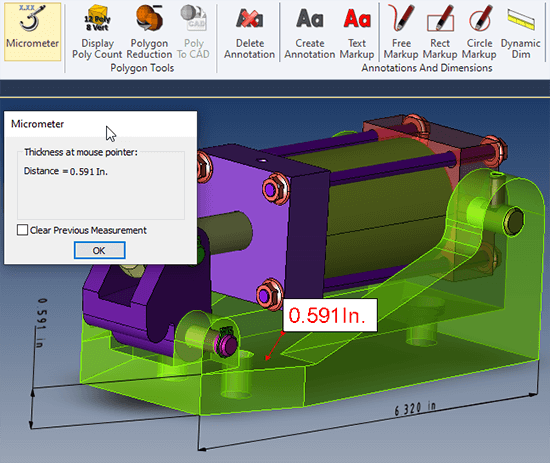
Easily measure and set dimensions using dimension and micrometer tools, and save views for downstream communications. Linear dimensions are added by clicking on one or two edges and placing the dimension.
Radial dimensions are added by clicking on any arc or curved face. If two arcs or circles are selected, a wizard is launched which guides you in hole-distance dimension placement.
Markup tools allow you to create temporary notes on the model or assembly.
Mass Properties, Surface Area, Bounding Box
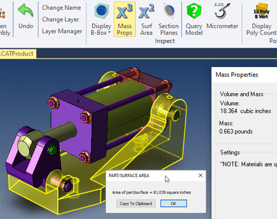
Interrogate Mass Properties, Surface Area, Bounding Box values. Mass Properties can be set on a per-model basis by right-clicking Materials in the Assembly Browser, and are based on the Units you’ve entered in Settings > General Settings.
All three queries are performed only on geometry that is pre-selected.
Settings
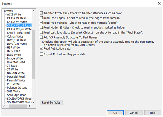
There are a wealth of settings for getting the CATIA or other formats just right when you read them with TransMagic. For example, if you are missing geometry, try enabling Read Hidden Entities (see Figure 7).
Read Publication Data should almost always be enabled – this is meta-data that can be important for design or manufacturing of the part or assembly.
There are similar settings for reading CATIA V4 parts and assemblies.
Writing Polygonal Formats
There are three core TransMagic products, and all of them can perform all of the CATIA Viewer tasks shown above. Typically TransMagic SUPERVIEW is considered the ‘Viewing’ product. All three core products can view all major 3D CAD formats, including CATIA, NX, UG, Pro/E, Creo, SOLIDWORKS, Solid Edge, Inventor, DWG and DXF.
SUPERVIEW writes all major polygonal formats including STL, OBJ, 3D PDF, WebGL and more.
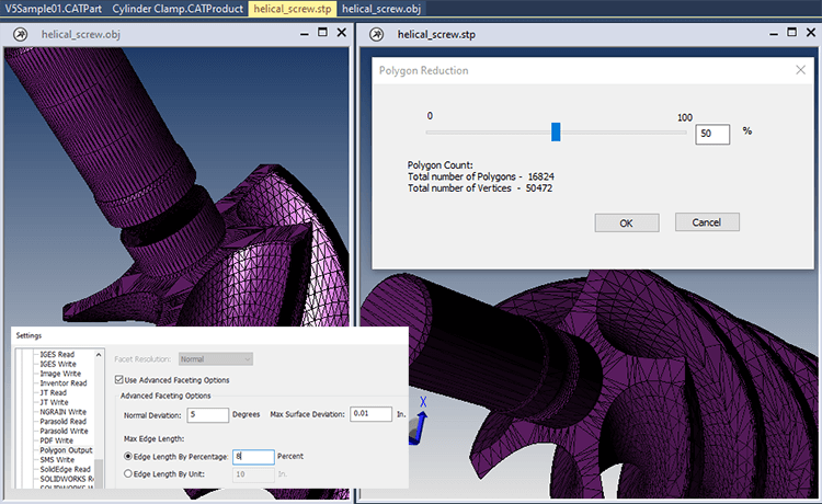
In Figure 8, two different methods of polygon optimization are shown; polygons can be optimized using Settings (for Polygon Output or STL Output), or by using the Polygon Reduction tool, which gives you a more intuitive sense of what the part will look like by dragging the slider shown on the right side of the image.
Writing CAD Formats
If you need to write to CAD formats, consider our other core products:
TransMagic PRO can write to neutral CAD formats such as STEP, IGES, Parasolid, ACIS and more.
TransMagic EXPERT can write to neutral CAD formats as well as native CAD formats such as CATIA, JT, SOLIDWORKS, DWG and DXF.
Try the TransMagic Eval
If you are not already using TransMagic, you can try the TransMagic eval by clicking here. The eval version includes TransMagic SUPERVIEW along with MagicHeal and MagicCheck. TransMagic SUPERVIEW will allow you to read all CATIA formats. If, for evaluation purposes, you need to be able to write to a CATIA format, or any other CAD format, submit the eval request form, and you will be prompted for that option. Alternately, you can discuss your needs with one of our account reps.
Related Articles
CATPart to STEP Covers a common translation scenario and the pros and cons of translating from CATIA to STEP.
CATIA File Converter Covers TransMagic’s CATIA File Converter capabilities.
The CAD Format Ladder and the CAD Format Ladder Part 2 cover why some CAD formats are better than others.
See a reference list of all CAD Extensions
See a listing of all the CAD formats TransMagic can Read / Write
Which Geometric Modeling Kernel? Covers the most popular modeling kernels and which CAD applications they power; it’s a handy list if you need to get the best possible CAD data to a customer or supplier who is using one of the listed applications.
IGES covers some of the IGES format’s many shortcomings in spite of the fact that it was a new, international exchange format that changed the world.