
by Brad Strong | Oct 23, 2017 | Blog, CAD Translation, What's New |
Assembly Restructuring allows you to work with the parts you have and restructure components as necessary to fit your design or manufacturing objectives. Being able to restructure assemblies gives you viewing and functional flexibility, even if you no longer have access to the originating CAD system. Where necessary, parts can be renamed, instance groupings can be broken, new subassemblies can be generated from existing parts, parts can be removed individually from subassemblies, true assemblies can be flattened and multi-body parts can be turned into true assemblies. Creating Assemblies from Multiple Solid-Body Parts Figure 1 shows a single part (with...
by Brad Strong | Oct 16, 2017 | 3D Printing, Blog, CAD Translation, What's New |
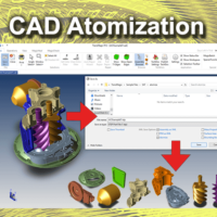
CAD Atomization refers to the process of converting whole assemblies to separate, independent parts. This is a one-button process which can be used for both CAD and polygonal output. 3D printing houses can use Atomize to output all parts in an assembly to STL. If you are planning to do polygonal output, be sure to check Settings and adjust polygon density before outputting STL or other polygonal formats. This article covers various STL output settings. The Atomization process works whether you are using an assembly or a multi-body part (multi-bodied parts are single parts composed of two or more solid bodies); in both cases, parts and bodies are converted to...
by Brad Strong | Sep 19, 2017 | Blog, CAD Translation, CAD Viewing, What's New |
The term ‘Digital Thread’ refers to a data and communications framework that passes through all relevant aspects of design, manufacturing, maintenance and disposal processes, providing an integrated and holistic view of assets throughout a product lifecycle. The Risk of Mixed Datums and Criteria Without a Digital Thread of product definition, manufactured parts might be designed with one set of datums and intents, manufactured using another set of datums and measurements, validated and checked using perhaps entirely new datums and criteria, and maintained with yet another set of systems and criteria. These criteria mismatches constitute a gap through which...
by Brad Strong | Sep 6, 2017 | Blog, CAD Repair, CAD Translation, Support, What's New |
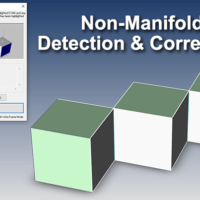
The MagicHeal Add-On for TransMagic now includes a powerful set of tools that help you with detecting and correcting non-manifold geometry. This is important because failing to detect non-manifold geometry can lead to problems downstream, when you are trying to use that geometry in a CAD system that does not support non-manifold geometry. What does Non-Manifold mean? Manifold is a geometric topology term that means: To allow disjoint lumps to exist in a single logical body. Non-Manifold then means: All disjoint lumps must be their own logical body. See a more detailed description of non-manifold geometry in this article. Two Non-Manifold Tools Show...


