 As mentioned in last week’s article, CAD files are rich sources of information which can be used to better understand and optimize the entire design and manufacturing process (see The Digital Thread article).
‘Informating’ is a term coined by researcher Shoshona Zuboff, who used it to describe, among other things, “computer-based, numerically controlled machine tools or microprocessor-based sensing devices (which) not only apply programmed instructions to equipment but also convert the current state of equipment, product, or process into data”. This newly available data can then be analyzed to gather new insights into our, in this case, design and manufacturing processes.
Whatever we choose to call it, analyzing the data we have at our fingertips though CAD systems and related processes promises to revolutionize how we design and manufacture.
How to extract data from CAD files using TransMagic
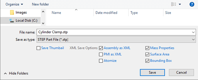
Figure 1 – XML Save Options
You can also see in this example that the format we are saving to is STEP. When you click the Save button, a CAD Brep file in the STEP format is created, as is an XML file with the same name, in the same folder. You can open the XML file with any ACSII editor; even Windows Notepad will suffice, but you’re better off with a code editing tool such as Notepad ++ or Komodo, which give you the benefit of formatting, color coding and speed.
TransMagic can extract the following forms of data from CAD files
- PMI (Dimensions, GD&T and notes)
- Mass Properties (mass, volume, centriod, moments of inertia)
- Bounding Box (X, Y and Z coordinates of any given part)
- Surface Area
- Assembly Part Data (part count, part names)
Let’s take a look at what some of this extracted data looks like. We’ll start with an assembly.
XML data from assemblies

Figure 2 – CAD Data Extraction Header
Line 1: Typical XML header
Line 5: The name of this assembly
Lines 6-9: The x, y and z values for the bounding box for the entire assembly
Line 10: The total number of top level parts in this assembly (part_count). This would not include any parts contained in subassemblies.
Line 11: The first part found, or the first subassembly in this case.
Lines 12-15: The bounding box for the part or subassembly
Line 16: The part count for the subassembly
Line 27: X position for the entire subassembly
Line 28: Y position for the entire subassembly
Line 29: Z position for the entire subassembly
Line 30: The scale factor for the entire subassembly
XML data from parts
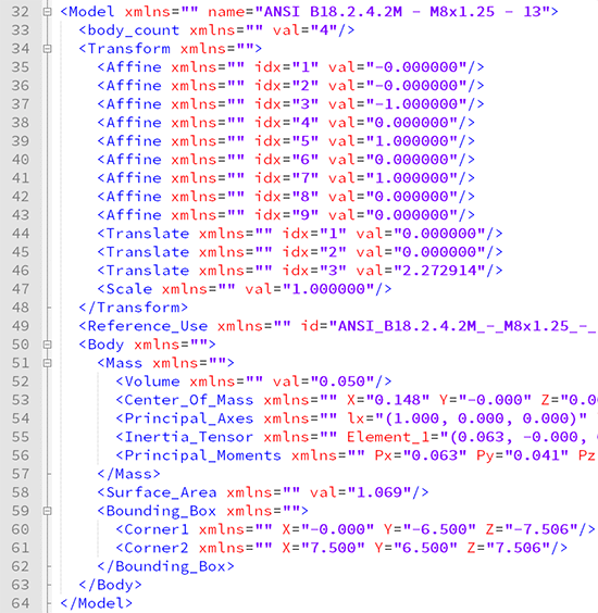
Figure 3 – CAD Data Extraction – Models
Line 32: The name of the model; in this case, ANSI B18.2.4 etc.
Line 44: X position.
Line 45: Y position.
Line 46: Z position.
Line 52: Volume
Line 53: Centroid
Line 54: Principle axes
Line 56: Principle moments of inertia
Line 58: Surface area
Line 60: 1st corner of bounding box
Line 61: 2nd corner of bounding box
Please note that data extraction is only available in EXPERT configurations of TransMagic. Evaluation versions of TransMagic are based on the SUPERVIEW configuration, and do not include the ability to save to CAD formats or to extract CAD data. If you’re interested in evaluating EXPERT, please contact TransMagic’s sales office at sales@TransMagic.com, give us a call between 8AM and 5PM Mountain time at 303-460-1406.
In a future post we’ll take a look at extracted PMI data, and delve into the benefits of ‘Atomize’. We hope this article has been of interest and invite your comments or questions at social@TransMagic.com.