 Part Manufacturing Information (PMI) is critical data that was formerly regulated to drawings, and is now available as a component of 3D CAD models.
Dimensions, GD&T (Geometric Dimensioning and Tolerancing) and notes provide the detailed criteria that make effective manufacturing possible.
Having this information as a part of the 3D model solves a long-standing problem in the design and manufacturing world, where parts and drawings were both necessary and could lose sync when only one was updated; stories abound of out-of-sync parts and drawings, resulting in manufacturing errors when the wrong set of data was referenced. By combining PMI with a 3D CAD model, there is only one source for all pertinent information.
PMI data can also be leveraged as a part of the Digital Thread, for optimization of design and manufacturing processes.
How to extract PMI data from CAD files with TransMagic
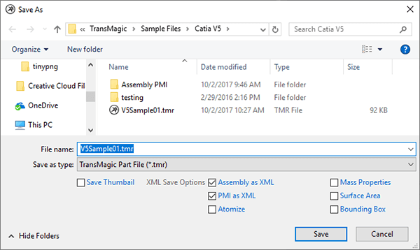
Figure 1 – How to extract CAD PMI data
To extract PMI data from any CAD file, start by making sure the file has PMI. In Settings, make sure that Application > PMI > PMI Options > Enable PMI Translation is enabled. Secondly, make sure that the PMI visibility toggle on the far right side of the Operations toolbar is activated. Both of these conditions are positive by default.
If you see PMI, you’re ready for the next step; if not, you may want to check with whoever sent you the file and have them verify that the file does indeed have PMI attached to it.
To write the PMI out to XML, from the Home tab, click Save As and select any CAD format. While the Save As dialog is still open, check the box labeled ‘Assembly as XML’ as well as PMI as XML. The XML data will be written to whatever folder is current in the dialog box.
PMI data from assemblies
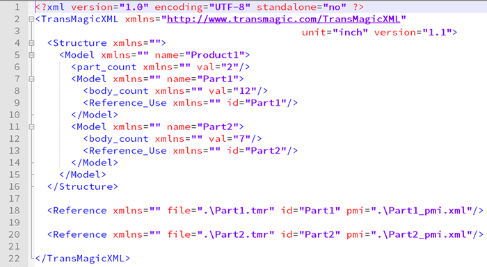
Figure 2 – How assemblies containing PMI parts are referenced.
Figure 2 shows the result if you extract PMI from an assembly; your main XML file will reference the part files that have PMI. Some of the key components of the assembly-level PMI file are:
Line 5: Assembly name
Line 6: Number of parts in assembly
Line 7: Part name
Line 11: Subsequent part name
Line 18: Reference for first CAD model and extracted PMI data
Line 20: Reference for subsequent CAD model and extracted PMI data
Linear GD&T example
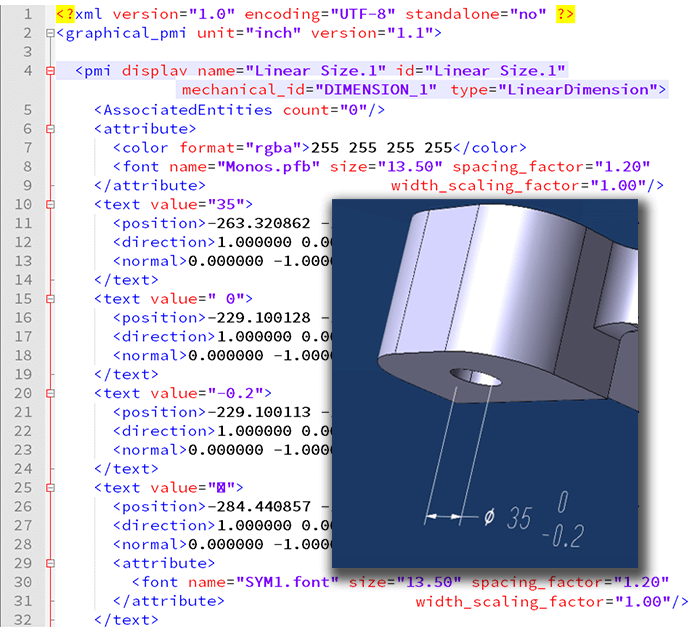
Figure 3 – PMI example
Figure 3 is a close-up screen capture of a NIST PMI hole dimension. Note that this example is made up of two extension lines, a dimension line, a dimension leader, a diameter symbol, a diameter dimension, a positive tolerance and a negative tolerance. This figure will be referenced in figure 4 below.
Line 4: The type of dimension; in this case we are looking at a diametric ‘linear’ dimension.
Line 7: Color for the PMI text; in this case, RGB of 255, 255, 255 (or, white). Note, you can change the PMI text and line color in TransMagic settings.
Line 8: Font used for PMI text.
Line 10: Dimensional text value of 35
Line 11: Locational position of the PMI text
Line 15: Maximum positive tolerance; 0 in this case.
Line 20: Minimum negative tolerance; -0.2.
Line 25: Diameter symbol
For information on extracting other CAD data such as mass properties, see the article on CAD Data Extraction.
Please note that data extraction is only available in EXPERT configurations of TransMagic. Evaluation versions of TransMagic are based on the SUPERVIEW configuration, and do not include the ability to save to CAD formats or to extract CAD data. If you’re interested in evaluating EXPERT, please contact TransMagic’s sales office at sales@TransMagic.com, give us a call between 8AM and 5PM Mountain time at 303-460-1406.
We hope this article has been of interest and invite your comments or questions at social@TransMagic.com.