by Brad Strong | Apr 10, 2017 | Blog, CAD Translation, CAD Viewing, Polygonal Output, What's New |
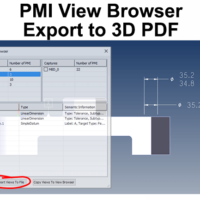
Exporting PMI to 3D PDF Exporting PMI to 3D PDF is a simple matter of choosing the PMI views you want to export, and clicking the Export Views To File button. The ability to export CAD views, along with associated PMI, makes communicating with internal and external team members who may not have a CAD system, or even a CAD viewer. 3D PDF is a great equalizer since the free Acrobat PDF reader is already installed on the vast majority of computers. In the first figure, there is one view selected in the PMI View Browser (MBD_02). This view is the ‘front’ view, containing three GD&T elements. Only the PMI for the selected view is visible, allowing...
by Brad Strong | Mar 27, 2017 | Blog, CAD Translation, CAD Viewing, What's New |
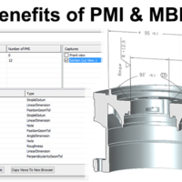
Product and Manufacturing Information (PMI) refers to metadata such as GD&T, dimensions and notes in the context of a 3D CAD model. Model Based Definition refers to the practice of using 3D CAD models, in association with PMI to define parts and assemblies without the need for drawings. In this article we will discuss some of the benefits of PMI and MBD. In future articles we will look at specific TransMagic tools for viewing and managing PMI. Benefits of PMI and MBD The ability to view metadata in the context of the part PMI allows you to clearly see GD&T, dimensions and notes in the context of the 3D model instead of in a separate drawing, making it...
by Brad Strong | Mar 20, 2017 | 3D Printing, Blog, CAD Translation, CAD Viewing, Polygonal Output, Support, What's New |
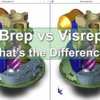
What are the advantages of Brep vs Visrep models, and how do you tell them apart? Brep Models Brep refers to Boundary Representation. As the name suggests, the boundary between solid and non-solid geometry is in view here, the solid geometry being a collection of interconnected surfaces. This is a mathematically precise representation of geometry. Depending on the format and the CAD software you have in your possession, the features and underlying sketches may be editable, or the shapes may be editable – but generally speaking, if you don’t have the CAD system used to create the file, you cannot edit the features or sketches unless you run a...
by Brad Strong | Mar 17, 2017 | Blog, CAD Diagnostics, CAD Translation, CAD Viewing, Support, What's New |
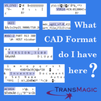
What CAD format, and what version, did that colleague just give you? Most of the time it’s clear what format it is, and most of the time the version doesn’t matter, BUT – sometimes it does. This is a repost from a few years back. It has turned out to be one of our most referenced resources, so here it is again! The following CAD Format Analysis cheat-sheet will allow you to open up CAD files in a text editor like Notepad or Notepad ++ to find out what format they truly are, and in some cases, which version. I’ve seen cases from some of our customers where CAD files had, for whatever reason, been given the wrong extensions; once we learn...

by Brad Strong | Mar 10, 2017 | Blog, CAD Translation, What's New |
CAD dimensioning tools allow you to add dimensions to vertices, edges and faces, whether they are linear, arcs, planes or cylindrical. You can place the dimension wherever you like, move dimensions after the fact, control what type of units are being displayed, the color of dimension text, and what views the dimensions show up in. In addition to CAD dimensioning tools, TransMagic has a host of capabilities which make the quoting and estimation process easier. These include: Markup tools for adding design or manufacturing notes to CAD models or assemblies Viewing tools to create custom views and select which dimensions are visible per view Rendering and...
by Brad Strong | Feb 27, 2017 | 3D Printing, Blog, CAD Performance, CAD Translation, Polygonal Output, What's New |
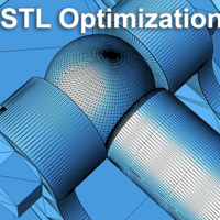
30 Years of STL From a humble beginning in 1987, when STL was developed by the Albert Consulting Group for 3D Systems, the format has been become a mainstay for 3D printing and has remained virtually unchanged over all these years. The name STL was derived from STereoLithography; STL uses a series of linked triangles to roughly define the surface geometry of a 3D CAD model. General STL Optimization Guidelines Whether you’re using the STL file for 3D printing, machining, or other purposes, you’ll want to set the resolution or mesh density to meet your product or prototype requirements. If your resolution is too rough, you’ll end up losing or...


