 CAD dimensioning tools allow you to add dimensions to vertices, edges and faces, whether they are linear, arcs, planes or cylindrical. You can place the dimension wherever you like, move dimensions after the fact, control what type of units are being displayed, the color of dimension text, and what views the dimensions show up in.
In addition to CAD dimensioning tools, TransMagic has a host of capabilities which make the quoting and estimation process easier. These include:
- Markup tools for adding design or manufacturing notes to CAD models or assemblies
- Viewing tools to create custom views and select which dimensions are visible per view
- Rendering and transparency support
- PMI viewing and management capabilities
- The ability to save models and assemblies out to 3D PDF and attach CAD data
Dynamic Dimensions
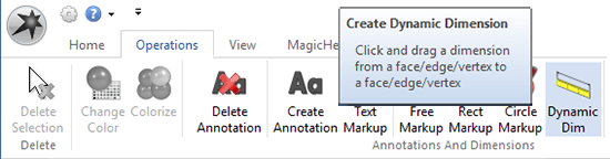
Figure 1 – Dynamic Dim is on the Operations toolbar.
CAD Dimensioning tools are found on the right side of the Operations toolbar, as shown in figure 1.
The Dynamic Dim button allows you to select vertices, edges or faces to generate radial or linear dimensions; simply select the geometry you want to dimension (select one or two edges or faces) with the left mouse button, move the mouse to move the dimension text, and left click to set the dimension.
Dimensioning a single edge or face
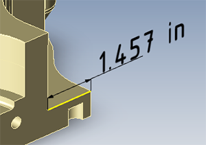
Figure 2 – A single linear dimension; just left click the edge and left click to place.
Left-clicking on a single edge or face will automatically generate a linear dimension for the length of the edge, a radial dimension if the edge is an arc, a diameter dimension if the edge or face is circular, and a radial dimension if the face is a partial cylinder. Figure 2 at right shows the result if the edge highlighted in yellow is selected.
The first click should be on the edge or face of your choice; at this point you can freely move the mouse and the dimension line and dim text will follow. A second left-click of the mouse will place the dimension. You also have the option, instead of placing the dimension, to click on a separate edge or face and thus generate a dimension between the two edges or faces.
Dimensioning between parallel features
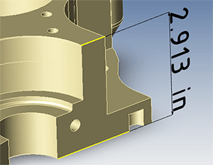
Figure 3 – Dimensioning Parallel Edges
Left-clicking on two straight edges or faces will allow you to create a linear dimension between those entities if they are parallel or an angular dimension if they are not parallel. In figure 3, both edges were selected with the left mouse button, which generates the dimension and allows the user to place the dimension with a third left-mouse click. As long as the Dynamic Dim tool is active, the dimension can be moved to new locations.
Angular Dimensions
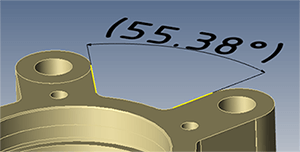
Figure 4 – How to achieve angular dimensions.
Selecting two non-parallel edges or faces will result in an angular dimension. In figure 4, note the yellow highlighting where two non-parallel edges were selected by the left mouse button; the dimension can then be placed with a third left-mouse click.
Angular dimensions can also be placed between two faces, or one face and one edge.
Dimensioning between two arcs or holes
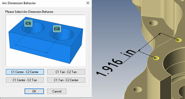
Figure 5 – Dimensioning between arcs or holes presents a few options.
If you select two holes or arcs (or any combination), you will be prompted for whether to dimension center to center, center to tangent, tangent to tangent, or tangent to center. In all cases, the dimension will be aligned to the angle between the two holes.
In figure 5 at right the center to center option has been selected with the result shown at far right. As long as the Dynamic Dim button is active, you can select on any dimension and move both the dimension line and the dimension text.
Dimensioning to vertices
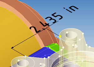
Figure 6 – Dimensioning to vertices requires that vertices are toggled ‘On’ on the View tab, under Rendering.
If you want to dimension from one vertex to another, or from a vertex to an edge or face, you’ll need to turn vertex display on. You can toggle vertices on via the View toolbar, in the Rendering area.
In figure 6 you can see a linear dimension being added between two points. Visible vertices are also necessary if you want to create a linear edge between two vertices (linear edge creation is only available in the MagicHeal add-on).
In this view the component being dimensioned is also transparent; if you need a component to be transparent, you can select it with the selection tool and set transparency via the Operations toolbar.
Micrometer
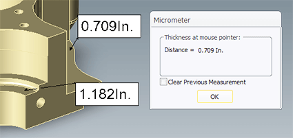
Figure 7 – The Micrometer tool measures thicknesses.
The Micrometer tool measures part thickness at a point perpendicular to the surface where it is selected. As with the Dynamic Dim tool, micrometer text can be placed anywhere, either at the time of dimensioning or after the fact. As long as the Micrometer button is active, any micrometer dimension may be moved by dragging with the left mouse button.
Note that the Micrometer dialog allows you to “Clear Previous Measurement” for situations where you are hunting around for the correct micrometer location. The other way to delete any dimension or micrometer value is to use the Delete Annotation button and select the unwanted instance.
Setting Units
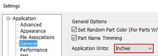
Figure 8 – Units can be set to inches, mm, cm, etc.
If you want different units to show up in your dimensions, set them in Settings > Application > General > General Options > Application Units. Inches, millimeters, centimeters, meters, feet, etc., are all available.
More quoting tools!
Upcoming posts will walk you through the use of additional quoting and estimating tools.
If this post raised any questions for you, drop us a line at media@transmagic.com and we’ll do our best to answer them.
If you’ve not tried TransMagic yet, there is a free eval available. To see which TransMagic product might be the best fit for your needs, visit the Product Wizard here, and to download an eval, visit https://TransMagic.com and click on the Free Eval link.