30 Years of STL

From a humble beginning in 1987, when STL was developed by the Albert Consulting Group for 3D Systems, the format has been become a mainstay for 3D printing and has remained virtually unchanged over all these years. The name STL was derived from STereoLithography; STL uses a series of linked triangles to roughly define the surface geometry of a 3D CAD model.
General STL Optimization Guidelines
Whether you’re using the STL file for 3D printing, machining, or other purposes, you’ll want to set the resolution or mesh density to meet your product or prototype requirements. If your resolution is too rough, you’ll end up losing or compromising some of the more detailed features such as small holes or bosses. Rough geometry can also necessitate additional finishing passes, either manually or with other machining processes, to get the model where it needs to be.
Optimizing STL for Machining
STL can work well for machining since STL as a format focuses only on surface geometry, sidestepping some of the mishaps that can take place when a CAD format is used; for example, if a fillet between two surfaces is not properly trimmed in the CAD format, some CAM systems can fail to see the fillet, and it can result in a gouged part. User error can also cause machining mistakes with CAD files; a part that looks good may actually be two disconnected parts, with devastating results when the tool “drops off” the first part. The triangles that make up the STL geometry do a dependable job of depicting any geometry in an unambiguous way, and in that respect they are great for machining.
On the other hand, an STL file is made up of faceted triangular elements, so you are never modeling exactly to the geometry of the original model; instead, you are modeling an approximation which differs from the original model by the tolerances you have set.
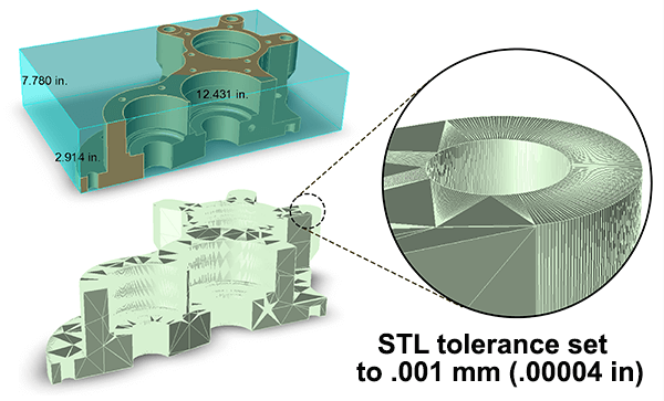
Just as with 3D printing, setting the STL density too low will result in an overly faceted model, and require too much post-processing work; it’s a good idea to set the STL output to match the lowest machining tolerance required for the part, though this can result in a fairly large STL file. STL model facet tolerances for machining purposes of .001 mm (.00004 inch) are not uncommon. In the example at right, this roughly 12x8x3 part has been converted to STL with a .001 mm tolerance and one area exploded to demonstrate the kind of faceting that you can expect. The original model, at upper left, has had a bounding box added to it to denote its actual size; this model, which was a mere 530 KB as a STEP file, balloons out to over 14 MB when converted to STL with a machining tolerance.
One thing you can notice is that the flat areas are minimally faceted, since they are already flat! The lion’s share of the density is in the curved geometry areas, or the edges of those areas.
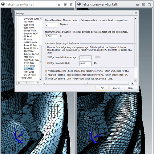
If you want to specify deviation tolerance before saving out an STL file, in Settings choose Formats > STL Write and set the value in Maximum Surface Deviation.
Optimizing STL for 3D Printing
Before you attempt to save a file out to STL for 3D printing, make sure the model is watertight, meaning that the geometry is complete and closed, with a definite inside and outside. This can be assessed in TransMagic by running the Auto Repair Wizard (ARW). If the geometry is valid, you will get the ‘green light’, representing a watertight solid.
Setting your STL file density also depends on the precision of the 3D printing system you’re using; in the figure at right, three settings are being used to increase the density of the STL output; Normal Deviation, Maximum Surface Deviation, and Maximum Edge Length Preference. Keep in mind is that the 3D print cannot be made any more resolved than your STL output, so it makes sense to err on the side of more density than less density.
Another article on optimizing for 3D printing comes from Sparx Engineering, who recently ran a study on the strength of different 3D print orientations, and found that rotating the part 45 degrees on the bed of the printer correlated with a noticeable increase in strength against breakage using a linear actuator press.
If you have the need to output multiple STL parts from a CAD assembly, look into TransMagic’s ‘Atomize’ feature. You can read more about CAD Atomization here.
Next week we’ll look at some other STL output tools and workflows.