by Brad Strong | May 10, 2016 | Blog, CAD Repair, CAD Translation, CAD Viewing, What's New
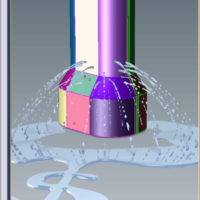
‘Six reasons watertight models matter’ makes the case that whenever possible, surface models should be converted to solid models. What is a ‘watertight’ solid model? Imagine your CAD model was made of ice, and we wrapped it in plastic wrap, the plastic wrap representing the surfaces on your part. If we now melted the ice, would the water be able to leak out? If so, you have a ‘leaky’ model, meaning the model is not watertight. What causes model leakiness? If any faces on the part are missing, or if you have any neighboring surfaces that are unstitched, you’ve got a leak. Visualizing a cube, if any of the six surfaces are missing, or if any two...
by Brad Strong | May 3, 2016 | 3D Printing, Blog, CAD Repair, CAD Translation, Polygonal Output, What's New
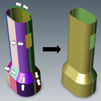
Eleven Techniques to Optimize 3D Printing CAD Files 3D printing and additive manufacturing processes are increasingly being used in to achieve quick turnaround on prototypes and to generate complex models cost effectively in low volume. Preparation of the geometry is the key to getting optimum results with 3D printing. The following techniques can shave hours off of the process of 3D printing CAD files. 1. Watertight Models Designs used for 3D printing need to be watertight solid models. 3D printers pre-process models into very thin horizontal slices of the part. Watertight geometry is necessary for the preprocessing step to avoid errors. Often,...
by Brad Strong | Apr 28, 2016 | 3D Printing, Blog, CAD Translation, Polygonal Output, What's New
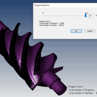
Polygon Reduction can have a Huge Impact on Productivity Polygon Reduction allows you to take any CAD or Polygonal model and reduce polygons for downstream uses such as 3D printing, Web parts libraries, animation, game development or other purposes. CAD, or Brep models: Brep (Boundary Representation) models are often incredibly detailed since they are often used to manufacture mechanical parts. Bringing this geometry into a 3d modeling and animation package like Maya, 3ds Max, Cinema 4D or Blender can be difficult due to all the polygons that are generated when the file is saved to a polygonal format. Polygon reduction eases this process immensely, allowing...
by Brad Strong | Apr 27, 2016 | Blog, CAD Translation, What's New
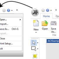
For basic translation and repair, TransMagic is pretty simple to use. Use ‘Open’ to open parts and assemblies, and Save As to save to the output format of your choice. But there are a lot of potential nuances to file translation and repair; where do you start? To answer that question, here are my top seven tips for new TransMagic users: Open and Import Open (see figure 1) is the simplest way to open any native or neutral format. In R11 and previous, the Open button had an upper and lower half (the bottom half was for ‘Import’), so it mattered which part of the button you clicked on. Import is useful if you want to import a file into...
by Brad Strong | Apr 26, 2016 | Blog, CAD Diagnostics, CAD Repair, CAD Translation, What's New
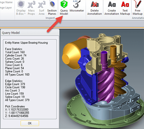
Quick Queries of Geometry and Graphical Feedback For this series, we’ve been looking into the diagnostic capabilitities of TransMagic. In this particular segment we look at two additional tools for geometry diagnosis that allow quick queries of geometry as well as graphical feedback. Click here to access earlier posts in this series, Diagnostic Tools for CAD Files Part 1 and Diagnostic Tools for CAD Files Part 2 and Diagnostic Tools for CAD Files Part 3. Query Model: The Query Model button is located on the Operations panel (see figure 1). This gives you the ability to query any model or body and returns the face and edge statistics, such as the total face...
by Brad Strong | Apr 20, 2016 | Blog, CAD Diagnostics, CAD Repair, CAD Translation, What's New
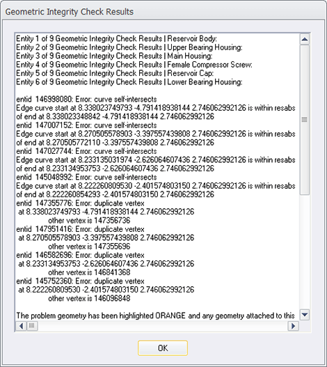
System Settings to Turn Off Repair and Turn On Diagnostics Note: This is the third article on Diagnostic Tools for CAD Files. This article focuses on how to turn off the normal repair feedback mechanism in TransMagic so that the diagnostic feedback becomes accessible. Click here to access earlier posts in this series, Diagnostic Tools for CAD Files Part 1 and Diagnostic Tools for CAD Files Part 2. In the early days of TransMagic, running any of the repair tools automatically generated a Geometric Integrity Check Results dialogue (see figure 1), which gave the user feedback about the integrity of each part in the assembly, and even drilled down to issues with...


