System Settings to Turn Off Repair and Turn On Diagnostics
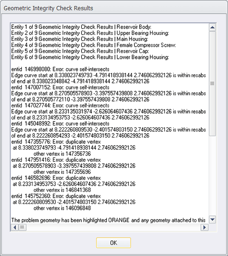
Figure 1 – Geometry Integrity Check Results
Note: This is the third article on Diagnostic Tools for CAD Files. This article focuses on how to turn off the normal repair feedback mechanism in TransMagic so that the diagnostic feedback becomes accessible. Click here to access earlier posts in this series, Diagnostic Tools for CAD Files Part 1 and Diagnostic Tools for CAD Files Part 2.
In the early days of TransMagic, running any of the repair tools automatically generated a Geometric Integrity Check Results dialogue (see figure 1), which gave the user feedback about the integrity of each part in the assembly, and even drilled down to issues with specific entity ids such as curve self-intersections or duplicate vertices. While this functionality was useful for some users, most users just wanted the repair process to be simple and automatic.
For that reason, the Auto Repair Wizard was developed which gives the user a red, yellow, or green light and a brief summary of the integrity of the file; the Geometry Integrity Check Results dialogue was removed, at least for the casual user. For users who still want to access this detailed summary of model integrity, the following steps will show you how to turn it back on.
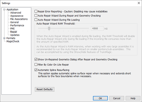
Figure 2 – TransMagic Repair Settings
Turn Off Auto Repair Settings To Trigger Diagnostics:To access this summary of part and entity integrity, simply turn off both auto repair checkboxes in Settings (see figure 2). Then, open a part or assembly and run the Auto Repair Wizard. You will get both the Geometry Integrity Check Results dialog, and the Un-Repaired Geometry Report dialog. Note: the Un-Repaired Geometry Report dialog comes up automatically, without having to turn off automatic repair settings.
Pre-select Geometry for Lite or Full Repair: You can also get results from running Lite and Full Repair the same way; it is worth noting, however, that Lite and Full Repair are both grayed out unless you have geometry selected. This is because you may want to run Lite or Full Repair on specific parts or bodies, as opposed to the entire assembly.
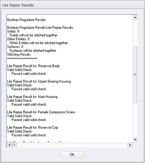
Figure 3 – Lite Repair Results
To select any part or body, simply use the selection arrow in the upper left corner of the screen. Note that it has a Dynamic Selection mode, and a Body Selection mode. The Dynamic Selection mode allows you to click once on a model to select a face, double-click to select a body, triple-click to select a sub assembly, and so forth. The Body Selection mode just selects whatever body you click on. Once you have pre-selected geometry, you will have access to Lite Repair (and Full Repair if you have the Magic Heal add on). An example of the Lite Repair Results dialog is shown in figure 3.