A Recent CAD Forum Discussion
Reading various CAD forums can be illuminating. Here’s a paraphrase of a discussion on a recent CAD forum where a CAD engineer is looking for a way to test if the original CAD model has been changed in any way when translating from CATIA to STEP to SOLIDWORKS.
So the question is, if CNC machining or other operations are going to be performed on models that were translated from the original, how do we know that those models are accurate? Let’s look at the question and some of the answers.
Question
We do aerospace design, and are sending a lot of models to subcontractors for CNC machining. During the CATIA to STEP translation, and then again when translating from STEP to SOLIDWORKS, we are seeing some areas changed. How do you guys verify that the translation was done well? Our CATIA support advised us to save the SOLIDWORKS file to STL so we can compare STL to the original CATIA model.
Answer 1
We compare COG, Volume and wet area.
Answer 2
We do a basic overlay of parts; assign the parts different colors and if they are the same, you’ll see a checkerboard surface of the two colors when they are exactly the same.
Answer 3
Take sections at specified locations and create points with specified distances, then compare coordinates.
Problems with these approaches
- Comparing STL to CAD Geometry: STL is a mesh of triangles (a Visrep or polygonal model), and would not get you an accurate comparison with the original CAD (Brep) model.
- Comparing Mass Properties:Comparing COG, volume and wet area might alert you to the fact that something has changed, but even if it does raise a red flag, you won’t know where the actual issues are.
- Overlaying Colored Models: Overlaying the original model and the translated model in different colors to look for changes is too crude a method to find minor variations, and even if it did work, it would be hard to use on internal surfaces.
- Comparing Sections: Taking sections and comparing point coordinates sounds time-consuming and tedious, and you’ll miss the actual changed area if it occurs between your sections.
A New Era
Twenty years ago, before there was such a thing as CAD Model Validation, some of these solutions might have had merit; but today you have the ability to let the computer do what it does best, while ensuring that there are no translation errors which could create problems downstream during the manufacturing process.
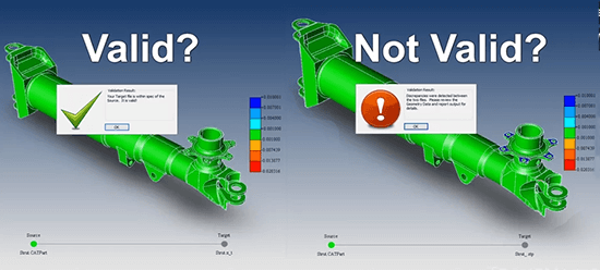
How involved is CAD Model Validation? Just open both parts in TransMagic MagicCheck, set your tolerance to .0005 or whatever you want, and click the Analyze button! In seconds (or minutes, depending on the part), you’ll have a heat map coloring all the areas where the parts are not in tolerance. Reddish areas indicate places where the check model is smaller than the original (authority) model. Bluish areas indicate places where the check model is larger than the authority model. If there’s a problem, you’ll see it, and the system will alert you immediately.
A report can be generated with the click of a single button. If you want to do Point-to-Part checking, MagicCheck does that too. Here’s a video that gives a quick overview:
Read more about using TransMagic MagicCheck to satisfy Boeing Spec D6-51991 here, and find information on AS 9100 spec here.
Click here to learn more about MagicCheck.
Test Drive TransMagic
If you don’t already own MagicCheck, you can test drive TransMagic SUPERVIEW, along with MagicHeal and MagicCheck Add-Ons for 7 days at no cost – just click this link to get to the free eval. If you don’t already own TransMagic PRO or EXPERT and need to be able to write CAD formats to do a proper eval, let us know at sales@TransMagic.com.