 TransMagic’s PMI to Wires allows you to write true PMI to ‘Wires’ or edges, so that the PMI content can be seen by anyone viewing any CAD format, from CATIA to Parasolid to STEP to IGES, giving you the flexibility to communicate your Product and Manufacturing Information to any customer.
A Review of PMI
 Product and Manufacturing Information (PMI) is becoming a critical part of the modern design process.
More and more companies are embracing Model Based Design (MBD), in which dimensions, notes, and other critical manufacturing data is applied directly to the model rather than held in 2D drawings. By tying PMI to the model itself, the risk of having out-of-sync drawings is eliminated, which also eliminates many downstream design and manufacturing errors.
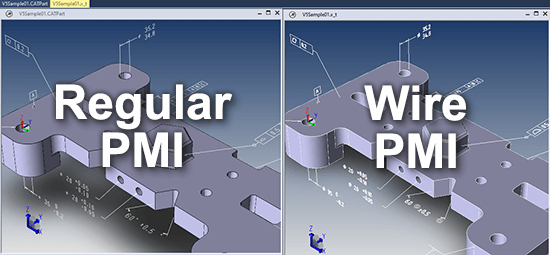
The problem is that sometimes customers cannot get true PMI data in the format of their choice. One solution is Wire PMI; as you can see in the comparison image for this article, Wire PMI looks just like normal PMI, but it is available for any CAD format at the click of a button.
Other Ways to get PMI
If you can write PMI to a CAD format, such as JT, and your customer can read JT, that would be one solution. You can also capture PMI with 3D PDF. In TransMagic, this is as simple as Save As and then selecting 3D PDF. WebGL, a lightweight data format which can run in any HTML5 browser, also supports PMI.
The weakness of 3D PDF and WebGL in some scenarios is that you are no longer dealing with a true CAD B-rep model, but a polygonal model, since 3D PDF and WebGL are polygonal (or Vis-rep) formats. So while polygonal models such as these can also include PMI, you can’t save them out to a CAD format, and you can’t perform mass properties and other kinds of precise operations on them, nor can you use them for various downstream CAD applications.
How to Create Wire PMI
Find the checkbox under Settings > Application > PMI > PMI Options. By default, Write PMI Out To Wires is disabled. By checking the box you enable conversion of all PMI to wires (or edges) in any newly saved CAD formats. Then just click OK to save your settings, and Save As to the CAD format of your choice!
You can see a visual example of Wire PMI on the first image in this article – regular PMI is on the left, and Wire PMI is shown on the right.
Make Sure Edges Are Enabled
 Since the PMI has been written to edges, you’ll want to make sure that the format you saved to has edges enabled before you open the actual file.
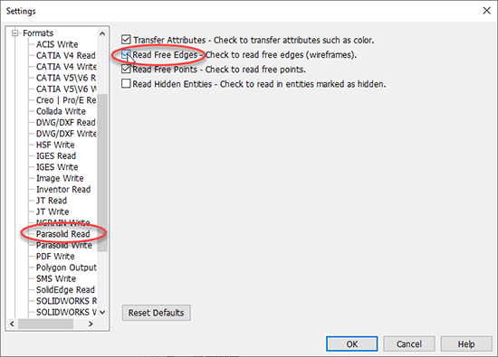
For example, if you saved to the Parasolid format, you’ll want to verify that the PMI was actually written to the Parasolid file – so before you open the Parasolid file to check, first go to Settings and, under Settings > Formats > Parasolid Read, and make sure that Read Free Edges is enabled.
Then open the Parasolid file and see if your PMI is intact. The Wire PMI uses an Edge font to depict all of the PMI information and make it viewable in all CAD formats.
Changing Edge Color
 If the ‘edge’ color is similar to the background color of your screen, it can be difficult to read PMI. For these and many other reasons, you may want to change your edge color.
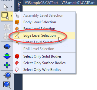
To do so, use the Select tools from the sidebar toolbar and select Edges from the drop-down list, then use a Selection Window to select all of the edge PMI; then, from the Operations toolbar, click Change Color and select your color of choice.
Both PMI and Edge PMI rely on contrast to be visible, so either changing the color of the PMI or Edge PMI entities, or changing the background color of the screen area (using the View toolbar > Top Color, Bottom Color) may be necessary.
Related Articles
- Benefits of PMI and MBD – Benefits include viewing PMI metadata, elimination of information redundancy, parsing viewing planes and annotated sections.
- How to View CAD PMI – Just the basics.
- Exporting PMI to 3D PDF – How to export PMI to 3D PDF from the PMI View Browser.
- PMI Data Extraction – How to extract PMI to an XML file.