 Product and Manufacturing Information (PMI) refers to metadata such as GD&T, dimensions and notes in the context of a 3D CAD model. PMI is a key component to MBD, or Model Based Design. It benefits design and engineering practices by tying the model metadata to the model itself, eliminating the need to maintain separate files for drawings, and making it easier to see where each dimension and tolerance note belongs. For more information on this, read Benefits of PMI and MBD.
Standard PMI Viewing
Normally, all you have to do to view PMI is to open the model in TransMagic. System defaults should allow you to see PMI, if it exists. If you want to see if the GD&T note is attached to a particular geometric feature on the model, just select the note with your left mouse button; the GD&T note will highlight, and depending on how the PMI was originally applied to the model, the associated geometry may highlight as well. Rotating and zooming the model will allow you to inspect all the GD&T values on the model.
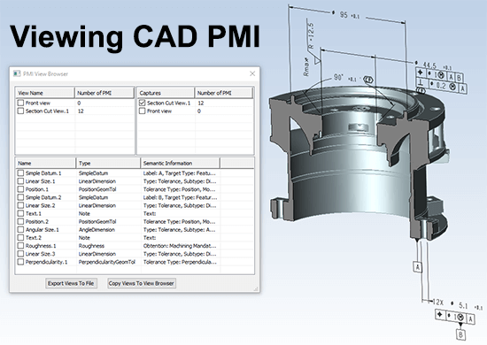
The PMI View Browser
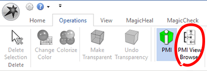
The PMI View Browser gives you much more functionality than standard PMI viewing; you can find the PMI View Browser at the end of the Operations toolbar in TransMagic (see figure at right). Notice to the left of the PMI View Browser launch button there is a PMI toggle that turns PMI on and off.
Benefits of the PMI View Browser

The PMI View Browser allows users to parse PMI into different views based on how it was created; this vastly improves usability, eliminating the ‘rats nest’ of notes that can clutter up a complex model or assembly. The figure at right shows a standard PMI view on the left, and a view of PMI using the PMI View Browser on the right; notice that the front view is active – this tool enables you to view PMI per view (typically there are six or more views which correspond to each viewing plane).
Another benefit of the PMI View Browser is the ability to show PMI for section views. Read more about related benefits of PMI and MBD here.
PMI Settings
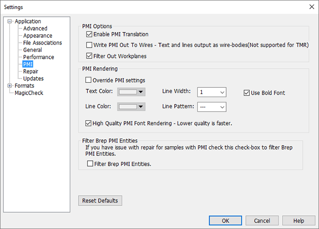
Under Settings > Application > PMI, you will find PMI Settings.
PMI Options
Enable PMI Translation is checked by default and enables PMI to be read.
Write PMI Out To Wires will create edge output that represents PMI graphically.
Filter Out Workplanes will ignore PMI related workplanes.
PMI Rendering
Override PMI Settings will override default PMI color settings.
Text Color, Line Color, Line Width, Line Patter and Use Bold Font all allow adjustments to PMI appearance.
Filter Brep PMI Entities
Filter Brep PMI Entities will filter out PMI entities at repair time to avoid issues.
Troubleshooting PMI
PMI should be viewable by default, but occasionally problems arise. If you can’t view PMI on your model or assembly, here are some possible causes:
- Enable PMI Translation may be turned off. To resolve this, open Settings and make sure the Enable PMI Translation button is checked
- The PMI button is disabled. To resolve, make sure the PMI button is enabled on the Operations toolbar.
- If you don’t see any PMI on your model, check with whoever sent you the model and try to confirm that there should be PMI attached to the model.
- Check to see if the PMI is just semantic, not graphical; you can do this by inspecting the file structure in the Assembly Browser.
As always, if you have questions or comments, please address them to social@transmagic.com.