We’re reviewing an article written by Stephen Wolfe on How to Choose a CAD System. Since a lot has changed since the article was first published, we’re noting what’s still of value as well as bringing in new information. For the first in this series, click here.
Here’s Stephen’s original list:
- Capable, efficient 3D design
- Compatibility with customers and suppliers
- Drafting tools that meet your standards
- Reliability and stability
- Built in applications that help your business
- Pleasant business relationships
- Short learning curve
- Innovative R&D to protect your investment
- A dealer who can help you
Compatibility with Customers and Suppliers
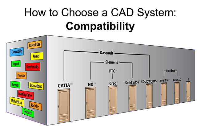
Customer and supplier compatibility is the next topic Stephen covers, suggesting that each company has a type of ecosystem it operates in; it makes sense to choose a CAD system that is popular in your ‘community’ so that translation of files is minimized. He further suggests that the CAD system of choice be capable of reading and writing formats such as STEP, IGES, VDA and IDF for easy transfer between systems. I’ll point out that VDA is a German standard for transfer of surface models which has been superseded by STEP, and we rarely hear about IFS today.
STEP Not Ideal: I’d also like to clarify here that though all major CAD systems can read and write the STEP format, but the STEP format is not always the best format for the job. According to our experience, you want to get the best possible format from your customer, and give them back the best possible format for their needs, which often means either the native CAD format (such as CATPart or CATProduct), or the kernel format (for example, Parasolid or ACIS). Further, it needs to be asked if the formats being created are good quality; there is such a thing as a good and bad STEP translation, for example. If the translation is not good, look for another CAD system, or consider a solution such as TransMagic, which is special-built for solving translation needs. To learn more about the best formats for each situation, read our CAD Format Ladder articles – the CAD Format Ladder part 1, and the CAD Format Ladder, part 2.
Editing Features
Another thing Stephen doesn’t address is that unless the customer data is in the same native format as your existing CAD seats, you’re not going to have access to those features, feature sketches, or assembly mates; what you’ll get is ‘dumb’ solids, positioned correctly. To edit these models in another CAD system, you have three options:
- Direct Editing: Begin editing the solid with new features, adding or removing features as needed but not having access to the original parametric dimensions or design intent. Several of the major CAD systems now have ‘Direct Editors’ which can make edits on non-native geometry without adversely affecting the underlying parametric features. More about this below.
- Feature Recognition: Use a feature recognition tool (all major 3D CAD systems have these) to process the ‘dumb’ solid until it has all or most of the defining features you need to edit. The success of feature recognition depends on the form & complexity of the geometry, the quality of the feature recognition tool and the skill of the operator.
- Use a Conversion Process: Use a software / service to convert the model to the format of your choice. This is a very expensive proposition and one we won’t go into here.
Digital Mockups
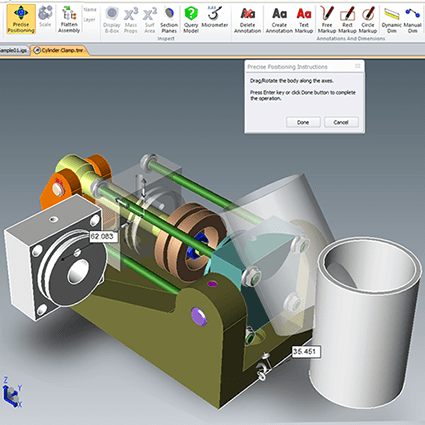 It’s important to remember in cases where you just want to create a digital mockup (and don’t need to edit model geometry) that you may not need a full-blown CAD system at all; TransMagic can open any major 3D CAD model and allows you to build new assemblies with disparate parts using ‘precise positioning’ tools.
Parametric vs Direct Editing
Almost all CAD systems are either Parametric/History-Based, Direct Editing, or have elements of both; Parametric Technology Corp (now PTC) was first to market with a parametric modeling system in 1988. It was not long before Solidworks followed with their 1995 release that became the first “mid range” parametric CAD system, and by 2000, all of the ‘Big 6’ (CATIA, NX, Creo, Solid Edge, SOLIDWORKS and Inventor) players had parametric CAD systems.
Siemens (the manufacturers of the NX and Solid Edge CAD systems) was the first of the big CAD companies to introduce Direct Modeling, but their ‘direct modeling’ has evolved into something they call ‘synchronous modeling’ which they say allows the user more flexibility when moving from parametric or ‘history based’ modeling to a direct model edit. Today, all of the big 6 CAD vendors allow direct editing in one form or another.
Direct Editing is useful when you need to import and use geometry that was created in a different CAD system; direct editing allows you to make changes to that geometry as needed without having access to the originating CAD system itself, by pushing and pulling on faces and features. While most of us will lean one way or the other, preferring history-based models over direct editing or vice-versa, industry experts believe having the option to carefully choose and apply the best solution for each case makes the most sense; for example, according to Monica Schnitger, conceptual modeling might lend itself better to direct modeling, whereas locking that model down to specific parameters might make more sense in later iterations to make sure design intent is not compromised.
Any CAD system decision should include an investigation into how feature and topology changes are effected, and how well that process fits company policies and needs. To help you sort through these questions, here are a few links.
Understanding Parametric Modeling Limitations: The Failed Promise of Parametrics: http://www.3dcadworld.com/the-failed-promise-of-parametric-cad/
Why History Based Modeling Still Matters: http://blog.grabcad.com/blog/2014/09/23/history-based-modeling-still-matters/
Resilient Modeling Strategy: The Resilient Modeling Strategy is a method of minimizing parent-child relationships in your history-based modeling approach to allow for the best downstream design flexibility: http://www.engineering.com/PLMERP/ArticleID/7495/The-Resilient-Modeling-Strategy.aspx
An overview of Direct Editing (2016): http://commons.erau.edu/cgi/viewcontent.cgi?article=1026&context=asee-edgd
Stay tuned for further articles on How to Choose a CAD System. If you have comments or questions, send them to social@TransMagic.com.