The need to compare CAD models
Imagine you are an estimator who works for a mold development company; a prospective customer sends you a CAD file and asks for a quote to have a mold made. You pull up the model on your CAD or viewing system, make a few measurements, and take your best guess at what it might cost to make a mold for this part. You send the quote to the prospect, and a few weeks later, they send you a revised part and ask for a new quote; they also communicate that the only change is the size of one hole.
Your inclination is to do a quick visual check to verify there are no other changes, and quote a similar price to the prospect, since this is faster than evaluating the entire part again.
Here’s where the problems could begin:
- There are more changes to the model than were communicated, which could drastically change the scope of the work, meaning that your company could ultimately lose money on the deal.
- The mold is manufactured but it’s designed wrong due to missed revisions. The customer won’t pay for it, leaving your company liable for costs on a part that nobody wants.
Different ways of comparing CAD models
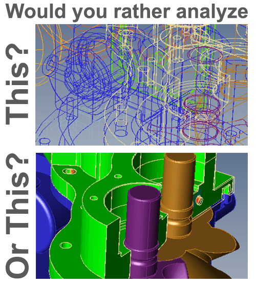
Figure 1 – Which would you rather analyze?
How do you compare CAD models to see what’s changed?
- The Brute-Force Approach: Take the original model, color it green, and switch it to wireframe display. Take the revised version, color it red, and switch it also to wireframe display. If possible, import one file into the other file so you can see them overlaid. Now visually inspect using brute-force eyeball strength to attempt to spot changes between the two. An approximation of this method is shown on figure 1.
- The Minimal Comparison Solution: Use the comparison software built into your CAD application. Some CAD systems have these and they are capable of rudimentary comparisons, but usually lack the precision, viewing area and robustness of dedicated solutions.
- The Purpose-Built Solution: Use a purpose-built comparison solution. One such example is TransMagic MagicCheck. MagicCheck will compare two CAD models, allowing you to select unit type, decimal precision, rendering style and generation of custom views; further, it will let you overlay the parts or display them side-by-side, toggle visibility between source and target parts, create a color heat map, and present a customized report of the analysis result. If you want to validate a part to see if it changed, it does that too, as well as point to part validations to inspect physical prototypes against the original master model.
How to compare CAD models
Comparing two CAD models is simple. In this article, we’ll look at the simplest case; two single parts. Here are the steps:
1. Open two parts
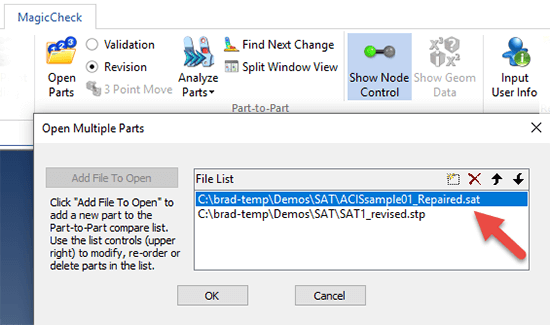
Figure 2 – Select two parts, and make sure the Source part comes first.
From the MagicCheck toolbar, choose Open Parts. Select both two parts (usually the original part and the revision you are checking it against).
Make sure that the original, or ‘source’ part comes first in order. If the parts come into the dialog box in the wrong order, use the arrow tools to move a selected file up or down in the list. This is necessary because when you analyze the parts, the source part is rendered to indicate where the revised part is out of tolerance to it.
2. Set your tolerance
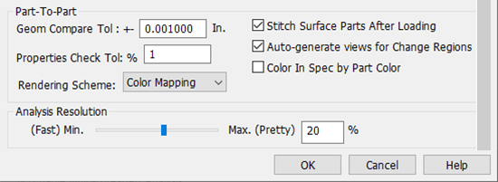
Figure 3 – MagicCheck Settings allow you to set your tolerance.
Both parts should now be overlaying each other on your screen. At this point, it’s a good idea to check MagicCheck settings for part-to-part.
In figure 3 you can see that tolerance is set to 0.001, or one-thousandth of an inch; if you work in millimeters or centimeters, you’ll want to change your unit type in the General Settings under Settings > Units. Anything outside of the tolerance you set will end up colored either a shade of red or blue.
3. Choose analysis type and click on Analyze
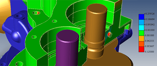
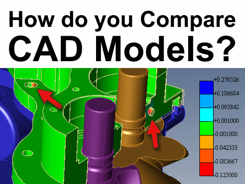
Figure 4 – A colored heat map indicates where two holes have moved.
Depending on the complexity of the geometry, the analysis can take just a few seconds, or much longer, even hours. Ultimately, you should end up with a colored heat map that shows areas where geometry is inside of the original part envelope (red) or outside of the original part envelope (blue), based on the selected tolerance.
In figure 4, both holes are colored red, meaning that they cut into the envelope of the original solid body.
4. If you want a report, click Create Report
There are tools to enter your company data and logo at the top of the report. Reports can be saved out as 2D PDF or 3D PDF.
Of course there is more to MagicCheck than this; you can parse through changes with the Find Next Change button, create custom views of areas of concern, split the window view so you can view both parts separately yet rotate and zoom them simultaneously, select the Source and Target nodes to see each respective model in rendered mode while the other model is shown in wireframe mode, dimension geometry and use the micrometer tool to generate part thickness values for both parts simultaneously.
That’s just what’s possible with Part-to-Part Revision Analysis; MagicCheck also does Validation Analysis, and Point-to-Part Analysis. You can read more about comparison in general on our comparison page, learn about Validation Analysis here, and see a video on Point-to-Part analysis here.