Even though IGES is getting very old, it is still one of the most popular CAD formats out there. What accounts for this popularity? For one thing, it’s been around for a long time, and there are millions of IGES files out there, some of which are still in use. Secondly, though IGES has an illustrious history, not everyone recognizes that IGES is in most cases the worst CAD format to use for exchanging data, so many people continue to use it; but more about that later.
The Argument for a Neutral CAD Standard
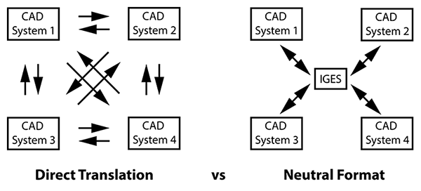
Fig. 1 – Direct translation puts an enormous burden on users, as compared to using a neutral format like IGES (or STEP).
The committee reasoned that since it was difficult for companies to enforce a single CAD standard across their offices and among all of their suppliers, there was a need for a “common format for neutral file exchange”. The argument was that a neutral format would ease the demands for data exchange.
In our illustration at right, inspired by the original IGES document, you can see that CAD to CAD translation requires each CAD system to be able to read and write to every other CAD system. Even if there were just four major CAD systems this would put a tremendous burden on each CAD system manufacturer.
The direct translation route, shown on the left, demonstrates that you’d need twelve separate translators to cover every contingency. The ‘Neutral Format’ solution, shown at far right, requires only eight translators to be written.
The formula for direct translators is N(N-1), where N is the total number of CAD systems you need to read and write. Where N is 4, you end up with 4×3, or 12 translators. As long as there are only four CAD systems, this is not that much higher than the formula for the Neutral Format solution; 2N, which comes to 8. But when you figure for five CAD systems, now you’re talking about 20 translators for the direct route, and only 10 if you employ a neutral format. If you have six translators, the numbers are 30 vs 12, and for eight, it’s 56 vs 16!
The bottom line is that a neutral CAD format makes a lot of sense for users and industry.
A Brief History of IGES
IGES began as an Air Force Integrated Computer-Aided Manufacturing (ICAM) initiative to reduce costs in all aerospace operations, back in 1976. Specifically, they were trying to solve the problem of incompatible CAD systems, and to bridge the gap between design and manufacturing. Those were the days when CAD dinosaurs like CADAM, Applicon, CATI (soon to be CATIA), SDRC, Anvil, ComputerVision and Intergraph roamed the earth. This process of solving CAD incompatibility was not easy.
Even back in 1979, when the few CAD systems of the world were less than 10 years old, it was becoming painfully obvious to users that there was no way to share data between systems. At an Air Force Integrated Manufacturing meeting in the fall of 1979, someone from General Electric challenged a panel of CAD vendors to work together to provide a way to share CAD data between them. While this was counter to each vendor’s desire to protect their own intellectual property and competitive advantages, a representative from ComputerVision returned the challenge to Boeing and General Electric, asking that they contribute any CAD translators they had already developed.
These challenges sparked conversations that went on into the night, and representatives from the Air Force, Navy, NASA and the National Bureau of Standards pitched in with their support. The IGES Organization was formed by the National Bureau of Standards the following year.
A Look at IGES
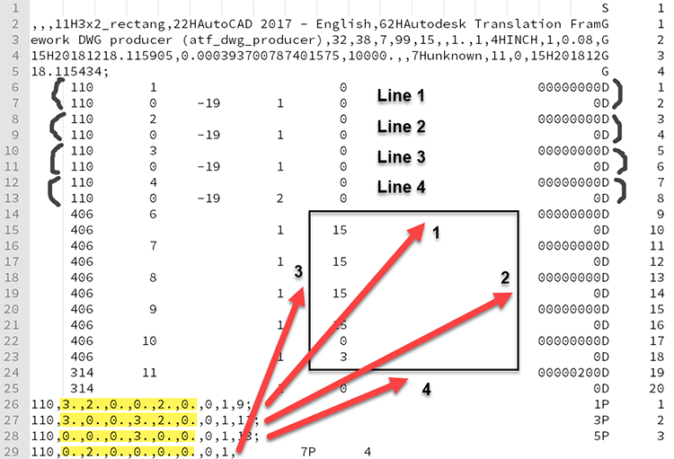
IGES files are long, so Figure 2 illustrates a simple example – four lines making up a rectangle. IGES files are 80 characters across, and are made up of four major sections: Start/Global, Directory Entry, Parameter Data, and Termination. The Start/Global is the header section, where you’ll find the name of the file, the system used to write the file and units used; in our example below, the Start section is on lines 2-5.
Next we have the Directory Entry section (lines 6-25). The first entities are lines – entity type 110. Positions 6 and 7 designate 20 possible attributes for the first line, and the XYZ values for the first line are given on position 26, in the Parameter Data section. Likewise, the second line is defined via positions 8 and 9, and the XYZ values for the second line are given via position 27. In this way, each entity appears twice in every IGES file, once for Directory Entry properties, and once for Parameter Data definitions.
In the Parameter Data section (lines 26-29 below), the XYZ values for the first line (entity 110) are highlighted in yellow; this describes the two endpoints of the line, at 3,2,0 and 0,2,0. This can be translated as an X value of 3, a Y value of 2, and a Z value of 0 at one endpoint of the line, and an X value of 0, a Y value of 2, and a Z value of 0 at the other endpoint of the line (see line 1 in the illustration).
Import and Export of IGES
The first thing to recognize about both IGES and STEP is that not all translators are created equal; of the two, IGES has even more “looseness” in terms of how the translator can be built, and that looseness can lead to problems; for example, once an IGES file has been written by a poorly defined translator, it doesn’t matter how good your IGES reader is on the other end. Typically, a file is first written, then read, and you’ll want the best quality you can get on both ends.
The second thing to consider are the Settings. Here are some of the settings available for IGES Import and Export in TransMagic:
- Transfer Attributes (such as color)
- Auto Surface Repair (repair individual surfaces upon read)
- Read Free Edges (this one is off by default)
- Read Free Surfaces (again, off by default)
- Read IGES Solid (reads Manifold Solid Boundary Objects)
- Write Free Edges
- Write Trimmed Surfaces
- Write All Surfaces as Spline Surfaces (IGES 128)
- Write All Curves as Spline Curves (IGES 126)
- Solid Output Type – Surfaces, Solids or Wireframes
- IGES Flavor – AutoCAD, SOLIDWORKS, JAMA, VX
What are some examples of how to use these settings? Let’s say you just received a file from a customer and nothing is showing up; that would be a good time to turn on all the switches (such as Read Free Edges) to make sure the file is really empty, and when you open it in TransMagic, from the Right Button Menu, do a Show > Show All. Then Zoom All, because most of us have seen cases where the geometry was off the screen, and a zoom all will let you see it.
Solid Output Type – You may have noticed from the list above that IGES is capable of creating solids; it’s true, but not used very often. However it does give you one more tool to try if your customer can write IGES Solids, and you can read them.
Write Free Edges – Why would you want to do that? You might be getting a file to a customer who is working with some somewhat old software which can only take IGES files, and they want to be able to view PMI (Product & Manufacturing Information).
Now, TransMagic has the ability to Read PMI, write PMI to JT and 3D PDF, and if desired, write that PMI out to graphical edges, so that anyone who can open an IGES file (or any other CAD file) can read it.
The bottom line is that settings can be massively important when bringing in problematic CAD data, as well as when moving data from one CAD system to another.
Once you get settings the way you want them, you can save them to a file by using Help > Export Settings File.
The Problems with IGES
IGES was developed very rapidly, at least partially due to the limited scope of the specification. And though it was a great first effort towards a neutral CAD exchange format, as soon as it was in the hands of users everywhere, weaknesses were exposed. These weaknesses included:
Flavorings – Flavorings refers to the inclusion of several ways to capture and interpret the same information, creating unnecessary ambiguity.
File Size – Large IGES files took long periods of time to process.
Lack of Formal Information Modeling – Doubtlessly one of the reasons IGES went so fast was also a shortcoming; the lack of a disciplined architecture, something STEP later addressed with EXPRESS and CDIMs.
Upward Compatibility – Each succeeding IGES generation needed processors to remain compatible with earlier IGES builds, making upward compatibility difficult.
Inability to Capture Complete Product Data – Is the circle shown in the IGES file the edge of a part or a hole? There was a recognized need for more understanding of what the lines, circles and arcs actually represented. This need to fully understand the design soon grew encompass MBD and PMI, which is becoming mainstream today.
Subsetting – It is possible to only partially implement IGES, a tactic employed by some vendors, which hurt the exchangability between systems.
Additional Issues with IGES
Some time ago I wrote Six Reasons to Avoid IGES. I will briefly summarize those points here:
- IGES is Old – IGES began in 1980 and the last official version of IGES was release in 1996. By comparison, STEP is still being revised today.
- IGES Geometry is not as ‘Information Rich’ as Solid Geometry – The vast majority of IGES files are surface models, which have no mass properties, surface area, are difficult to dimension, and do not support notes and tools to add manufacturing information to the file.
- IGES files are Difficult to Edit – Ever try to edit a surface? Once you’ve been spoiled by editing solid models, going back to surfaces is difficult.
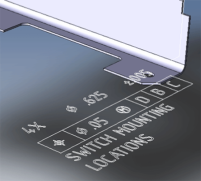
- IGES cannot carry MBD / PMI Data – The design and manufacturing world is slowly shifting towards MBD (Model-Based Definition) to define all aspects of the design in the CAD model. This includes PMI (Product and Manufacturing Information) which lets users see dimensions, GD&T, and notes right on the 3D model. MBD allows for all the information to be in one place, rather than split into two places (models and drawings), thus eliminating the risk of having out-of-sync data which could lead to manufacturing errors.
- Downstream Applications Prefer Solid Models – This would include Machining, FEA, 3D Printing, etc.
- IGES files often need to be Repaired – IGES are almost always surfaces, and surfaces do not know about neighboring surfaces, and gaps between surfaces can easily develop during translations and other operations. Solid are inherently solid and watertight.
Many of the shortcomings of IGES were resolved in STEP, a standard which continues to evolve even today. The vast majority of the time, you’re going to get better results with STEP than you will with IGES.
Nevertheless, we honor the CAD heroes who took the first bold steps into the unknown back in 1978 to develop what would soon become IGES, because IGES solved a multitude of exchange problems and ultimately made STEP possible.
The CAD Format Ladder
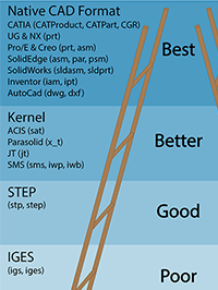
There is a hierarchy to CAD formats, and the ideal is to prefer the native format, then the geometric modeling kernel, then STEP, and last of all, IGES. You can read more about this hierarchy in The CAD Format Ladder. Many companies do not embrace this hierarchy because it is just not feasible to have all CAD systems and versions in-house; but TransMagic gives you the freedom to read and write more formats, and so can become your hub for 3D CAD interchange.
A free trial is available here. This version will open all major CAD and polygonal formats, but only writes polygonal formats; so if you need the ability to write CAD formats, once your eval has started, you can email license@TransMagic.com and request an upgrade to Expert.