by Brad Strong | Apr 12, 2016 | Blog, CAD Diagnostics, CAD Repair, CAD Translation, What's New
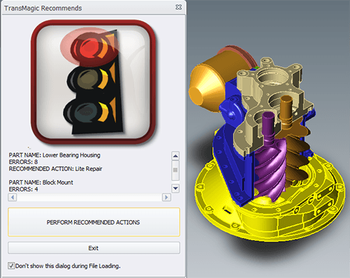
The Red Light and Error Feedback Note: This is the second article on Diagnostic Tools for CAD Files. This article focuses on what happens when you use the Auto Repair Wizard to repair a model and get the ‘red light’. Click here to access the first post in this series, Diagnostic Tools for CAD Files Part 1. The Red Light: Whereas the yellow light indicates open circuits where geometry is missing, the red light indicates more extreme problems such as bad vertices, bad edges, or self-intersections. Some of these problems can be fixed with Lite Repair, and some require Full Repair. Let’s look at a specific example (see figure 1). This SAT file has...

by Brad Strong | Apr 5, 2016 | Blog, CAD Diagnostics, CAD Repair, What's New
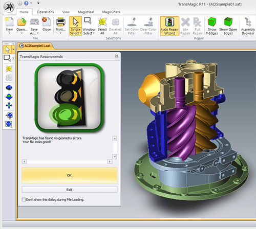
Using the Green Light as an Indicator of Quality Geometry Most TransMagic customers use TransMagic for viewing and quoting, translation between CAD formats, file repair or file comparison. Recently we found that some of our customers are using TransMagic’s features as diagnostic tools for CAD files to quickly determine the quality of their CAD files. If the file gets the ‘green light’ (see figure 1) and thus is found to be watertight, they know the CAD geometry is high-quality, and they send the geometry to design and engineering teams for further processing using a variety of CAD solutions. If the file gets the yellow or red light, it is not...

by Brad Strong | Dec 15, 2015 | CAD Comparison, CAD Diagnostics, CAD Validation, What's New
“Protect your downstream manufacturing investment with Point-to-Part Comparison, Part-to-Part Comparison, and Part- to-Part Validation” MagicCheck CAD model comparison software quickly opens all major 3D CAD formats, including point data, to compare against the source CAD model and analyze accuracy. Produce validation, revision and inspection reports for quality control processes. Find errors early while they are still manageable. What’s A Good Fit For MagicCheck? Job Shops and service bureaus who need to verify customer revisions to ensure no unexpected changes are missed. Prototyping specialists who need to compare scanned points against the CAD...

by Brad Strong | Sep 16, 2013 | Blog, CAD Diagnostics, CAD Translation, What's New
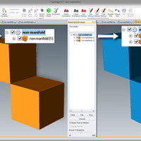
That is, what is Non-Manifold Geometry vs Manifold Geometry? The Meaning of ‘Manifold’ Manifold is a geometric topology term that means: To allow disjoint lumps to exist in a single logical body. Non-Manifold then means: All disjoint lumps must be their own logical body. Of course that definition is often more confusing so perhaps the best way to think of Manifold and Non-Manifold is this: Manifold essentially means “Manufacturable” and Non-Manifold means “Non-manufacturable”. In other words manifold means: You could machine the shape out of a single block of metal….and with a non-manifold shape you could not. Example...


