That is, what is Non-Manifold Geometry vs Manifold Geometry?
The Meaning of ‘Manifold’
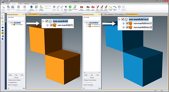
Figure 1 – Manifold vs Non-Manifold examples.
Manifold is a geometric topology term that means: To allow disjoint lumps to exist in a single logical body. Non-Manifold then means: All disjoint lumps must be their own logical body. Of course that definition is often more confusing so perhaps the best way to think of Manifold and Non-Manifold is this: Manifold essentially means “Manufacturable” and Non-Manifold means “Non-manufacturable”. In other words manifold means: You could machine the shape out of a single block of metal….and with a non-manifold shape you could not.
Example of Non-Manifold Geometry – Using TransMagic
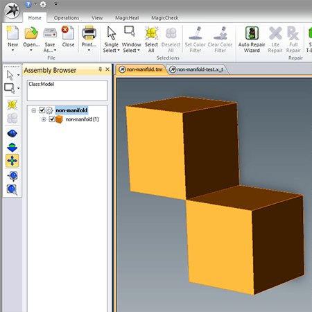
Figure 2 – Non-Manifold Body Example
This file consists of two cubes that were Boolean United along a single shared edge – resulting in ONE logical body. This is a simple yet effective illustration of a non-manifold body – where each block is a “disjoint lump” yet there is a single body. The shared edge between the blocks is the actual non-manifold condition. Since this edge is infinitely thin there is no manufacturing process that could create such a shape as an infinitely thin edge can not be manufactured. In reality, eventually you’d just separate the two blocks.
TransMagic is an example of a non-manifold geometry engine – a math engine where these types of shapes are allowed to exist. Modeling engines can be non-manifold or manifold, and it is also possible to have a manifold modeling engine that has non-manifold tools. Manifold modeling engines are not allowed to represent disjoint lumps in a single logical body. Each lump must be its own body.
Comparing Manifold and Non-Manifold Geometry
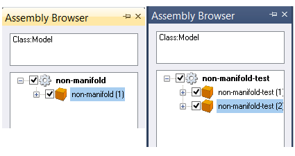
Figure 3 – Comparing Non-Manifold to Manifold
The screenshot at right shows what you will see in the Assembly Browser with formats which allow non-manifold geometry on the left, and formats which do not allow non-manifold geometry on the right.
When using a non-manifold modeling application during the creation of very large and complex parts it is possible that non-manifold conditions get created inadvertently from operations such as Booleans, blending, sweeping, lofting, shelling, etc. When TransMagic takes these very large and complex non-manifold solids and saves them out to a manifold modeling format – these conditions will necessarily need to be “split” at the non-manifold locations. When solids can’t be created then a surface model is created. It’s simply a matter of communicating two different mathematic models and this splitting cannot be avoided.
Detecting and Correcting Non-Manifold Geometry
TransMagic R12 has added a tool to make dealing with non-manifold geometry easier. Read about TransMagic’s tool to detect and correct non-manifold geometry here.
TransMagic Free Eval
If you need to open, view, repair, translate or compare CAD or polygonal files, TransMagic has (as of this writing) a free 7-day eval. Learn more about TransMagic here.
Related Articles
Advanced Repair Tools – TransMagic’s advanced repair tools for healing open gaps in models and other issues.
A Classic Repair Scenario – A step-by-step process to move from bad surfaces to good quality solid model.