 Today, it’s a multi-CAD world, and it’s good to know the best way of dealing with every situation.
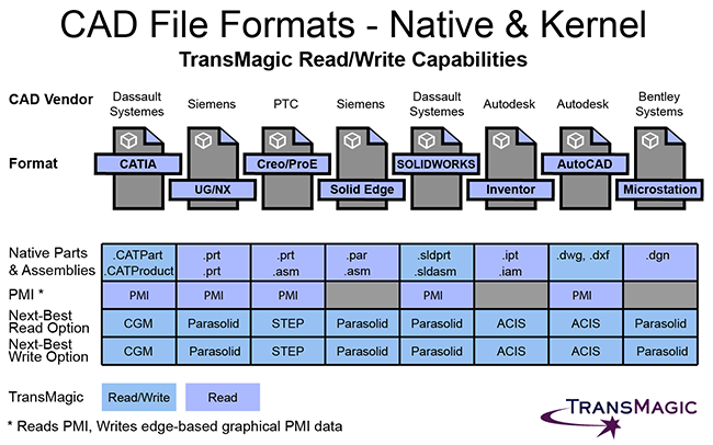
Though this graphic reflects the read/write capabilities of TransMagic, the article is written for the benefit of anyone who is dealing with a multi-CAD environment and needs a multi-CAD solution, whether you have CAD translation software in addition to your CAD system or not.
Ultimately, we suggest that you consider the information in this article, weigh it against the data you get from customers and suppliers, and define a process that guarantees that your team will be working with the best CAD data possible.
Go Native When Possible
It’s always best to use the native CAD format when possible; if your customer is Boeing, and they are sending you CATPart and CATProduct files from CATIA, it’s helpful if you have a seat of CATIA on hand to see the files in their native form.
However, not everyone can afford one or more seats of CATIA, so that’s where having access to a tool like TransMagic comes in – TransMagic allows you to open the CATPart and CATProduct CAD geometry without having to convert them to some other format. With TransMagic, you get essentially a seat of CATIA under the hood, at least in terms of translation capabilities – and that’s one of the reasons that the TransMagic install is now over 700MB.
Getting the best file is not always easy, but when you can, always ask for the native format from your customer, since that will have the most information and be less likely to have been compromised by the hazards of translation.
Native Parts & Assemblies
The Native Parts & Assemblies section can be helpful because it lists out what each native CAD format uses for file extensions for parts and assemblies. It’s noteworthy that UG and NX use .PRT for both parts and assemblies, which can be a little confusing. AutoCAD and Microstation do not have a separate file extension for parts and assemblies, reflecting their origins as general design CAD systems.
It’s always best to translate from and to the native format when possible, because the further down the CAD Format Ladder you go, the more information you lose.
Not sure what kind of format you have in your hands? What CAD Format Do I Have Here shows you some ways to find out what format you’re dealing with, and our CAD File Extensions article covers all known CAD file extensions.
Geometric Modeling Kernels
Geometric modeling kernels are the foundation upon which each CAD system rests. The kernel includes model creation and editing utilities for feature modeling, surfacing, blends, fillets, rendering and more. Geometric modeling kernels are written more precisely than neutral translation formats like STEP or IGES, so there is not very likely that you will run into a poorly written Parasolid or ACIS translator. If you have the ability to read or write to the kernel format of any given CAD system, it is the next best thing to having access to the actual native format. If you can’t get the native CAD format from your customer, try to get the geometric modeling kernel format (assuming you can read that format).
For example, TransMagic R12 SP2 added the ability to read and write CATIA’s XCGM kernel; this gives you one more way to receive from, or send data to a customer. Read about the latest additions to TransMagic R12 SP2 here, or see a list of supported formats here.
Parasolid is the dominant solid modeling kernel on the market today, at least as far as the Major CAD systems are concerned. Two other solid modeling kernels used in many CAD-related products are ACIS and SMLib. Though Autodesk decided to control their own destiny in 2001 by forking the ACIS kernel into Shape Manager, Shape Manager still operates very well with ACIS (*.SAT) version 6.
Product and Manufacturing Information (PMI)
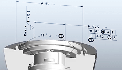 Product and Manufacturing Information (PMI) is probably the most visible element of Model-Based Design (MBD), a relatively recent movement which ties dimensions, notes and Geometric Dimensioning and Tolerancing (GD&T) information to the actual 3D model.
The big benefit of PMI is that you can see right on the model what different dimensions and tolerances are, rather than having to refer to a separate drawing; so the critical data is clearer, and there is no risk of having the same information in two places, and having out-of-sync data, which can lead to manufacturing errors.
TransMagic’s PMI View Browser has the ability to show PMI sections (see screenshot); this capability was driven by the needs of a major automotive manufacturer. PMI sections allow that manufacturer to keep one master version of all 100+ hole details tied to the CAD model and steer clear of downstream manufacturing disasters due inaccurate data. Read about more PMI Benefits here.
Wire PMI
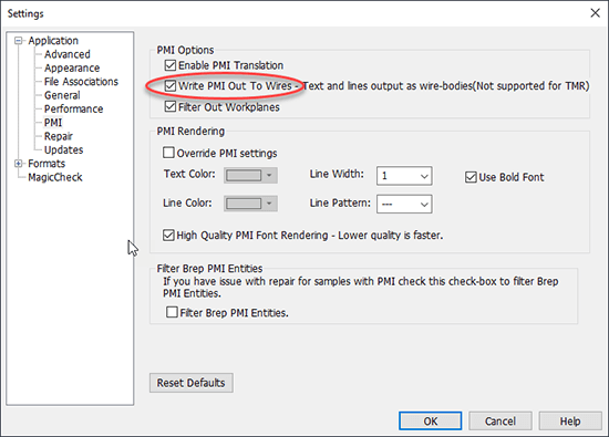 Wire PMI is graphical PMI that can still communicate the information contained in the PMI notes, but it is non-intelligent. All of the PMI information has been converted to edges, or ‘wires’.
To use wire PMI, open TransMagic Settings > Application > PMI and check the box Write PMI Out To Wires. The next time you save out a file containing PMI to any CAD format, the file will include edges showing the PMI data.
Keep in mind that if you write wire PMI out, you will need to include edges on your File Import settings; for example, if you wrote wire PMI out to STEP, you will want to enable Read Free Edges when opening the STEP file.
TransMagic can write wire PMI to every CAD format in their supported formats list.
Other ways to write out PMI
There are a few additional ways to communicate PMI information, in addition to those listed in the graphic above.
- Write the PMI to 3D PDF. 3D PDF supports PMI output. See an example of how to write PMI out from the PMI View Browser here.
- Write the PMI to Web GL.
- Write the PMI to JT. The JT CAD format can carry true PMI data when being read or written.
- Write the PMI out using PMI Extraction; this functionality is only available in TransMagic Expert, and writes the PMI data out to XML.
Best Read Options
As the graphic above shows, your best Read option for each format always starts with the native CAD format. If you can’t read the native CAD format, you should seriously consider a solution such as TransMagic in order to get closer to the original data your customer is giving you.
The second choice is almost always the geometric modeling kernel; for example, if you don’t have the ability to read a native NX .prt file, see if you can get the file as JT or Parasolid, because Parasolid is the geometric modeling kernel that the .prt file is built upon, and JT is another Siemens format which is also built upon the Parasolid kernel.
Best Write Options
 Your best Write options really depend on what your customer prefers, but would normally be the native CAD format, then the kernel format, and finally STEP.
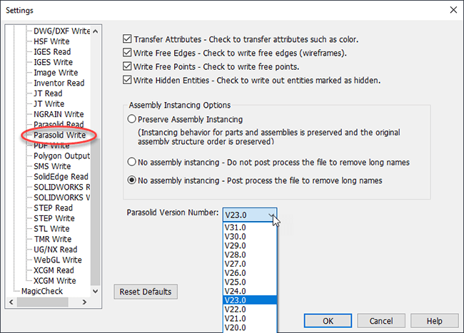
Looking at the screenshot to right, making sure you have the correct settings for your customer can make a big difference in how successful they will be. You can see that there are checkboxes for attributes, edges, points and hidden entities, as well as assembly instancing and Parasolid versions.
You can also see in the figure that the default Parasolid version is V23.0, which is a few years old by now; using an older version of Parasolid increases the likelyhood that the customer will be able to read the file, since CAD systems almost never backward-compatible.
On-Demand
The design and engineering team’s access to read and write CAD formats should ideally be ‘on demand’ so that there is no waiting to get started on or complete a work task. If team members do not have this quick access to optimal CAD formats, it can delay projects and tempt users to compromise by working with less desireable formats such as STEP and IGES. Today’s flexible networked licensing capabilities make it possible to give an entire team access to a floating license which can be used ‘as needed’.
TransMagic Read / Write
The Read/Write color coding in the first figure indicates where TransMagic can Read and Write the formats, or just Read the formats. Because the focus of this list is the major CAD systems, some important supported formats such as JT, ACIS and SMLib were not included; however, for a full list of supported formats, visit our CAD Formats page.
Neutral CAD Formats
If you can’t work with the native CAD formats, and you can’t make a geometric modeling kernel format work, there is always STEP.
The quality of a STEP translation depends on how good the STEP translator was written. If you do use STEP, you’re doubly exposed; you have to count on the STEP translator that writes the file into the STEP format before you get it, as well as the STEP translator you use before sending it back to your customer.
Last of all there is the IGES translator, which is still used more widely than you’d expect for a standard which was superseded by STEP in the 90s.
For more information about why not to use IGES, see this article. For the history of the IGES format, click here.
Test Drive TransMagic
If you haven’t tried TransMagic yet, try the free eval. You’ll have the power to read any major 3D CAD format on the planet, and write to 3D PDF and Web GL. If you need the ability to write CAD formats for your eval, or would like to learn more about ‘on demand’ network licenses for your team, contact Sales@TransMagic.com.