 In Six Reasons to Avoid IGES Files, we made the case that IGES, at 20 years old, is no longer an optimal format for manufacturing. In this article we’ll look at three categories of format that have proven success in manufacturing.
The best alternatives to IGES, in order of preference:
#1 – Go Native
There is often a reasonable bridge to be found between the format you’ve been given and the CAD system you need to bring it into. The best possible workflow is to get the native file from your customer or supplier, open it in your CAD system and make the necessary edits, and then give it back to the customer or supplier in their native format again. For example, if you received a part from Boeing, it would probably be a CATIA file in CATPart or CATProduct format. Open their CATIA file, edit it in SolidWorks (or whatever CAD system you are using), and when you are done, save it out in the CATPart format and send it back to them. In this scenario, as long as your CAD translation tools include the ability to read and write the CATIA format, you should be in good shape.
#2 – Use the Kernel or JT
All CAD systems have a core geometry modeling engine, or modeling kernel. Some CAD systems use proprietary modeling kernels, and some use popular licensable kernels such as Parasolid (.x_t) or ACIS (.sat). In many cases it is not possible to translate native to native, in which case it can make sense to use a modeling kernel format as an intermediary. Modeling kernels are almost always better than STEP files because they have strict rules about how they can be written. For much the same reason JT can be a good interoperability format for CAD systems that can read or write it. While JT is not a modeling kernel per se, it is a well-defined CAD format. One caveat with JT is that you need to be sure your JT file contains Brep (boundary representation, or solid model) geometry, because some JT files only contain Visrep (visual representation, or polygonal) geometry.
#3 – STEP Right Up
If you do not have the possibility to translate using native or modeling kernel formats, STEP is your last reasonable format to use to transfer CAD B-rep data, and in that capacity STEP has been a workhorse that has served the CAD community well over the last few decades. It’s rarely a better choice than using the kernel because there are many different STEP translators out there and a lot hangs on how good the translator is on your system. There is a lot of latitude in how a STEP translator can be written. Pro/E for example, was in the past well-known for its robust STEP translator; other CAD/CAM/CAE systems often have less robust STEP implementations.
It is important to remember that the STEP translator issue can affect you when writing and when reading the files. You write a STEP file (usually with the STEP translator that comes with your CAD system) and send it to your supplier, then they read that file (usually with the STEP translator that comes with their CAD software) and now a lot is riding on how well both STEP translators are able to read and write the data. And we haven’t even talked about going round-trip yet. An example of a round-trip translation would be where the supplier gets a file from the customer, performs some kind of design work on the file, and then sends the file back to the customer. In such cases you are now dealing with up to four separate translations. There is enough latitude in how a STEP translator can be written that STEP has a higher risk of translation problems than native formats, modeling kernel formats, or JT.
Translation Scenarios
Here are some scenarios that might be helpful in understanding how to use modeling kernels or JT files to move CAD data around
– The customer has Inventor
You may need to send a file to someone who uses Inventor, but you cannot write an Inventor .ipt or .iam file, so the next best thing would be to send them an ACIS file, since Inventor’s modeling kernel was originally derived from the ACIS modeling kernel.
– The supplier needs a file for Mastercam
A supplier may need a file for Mastercam; if you can’t write a native Mastercam file, send them a Parasolid file, since Mastercam is based on the Parasolid kernel.
– The customer needs a file that can be read by NX
If you can’t provide a native NX file to your customer, either JT or Parasolid should work quite well, since NX uses JT as an interoperability standard, and NX also happens to use the Parasolid kernel for its solid modeler.
Any Complex Workflow Requires Tuning
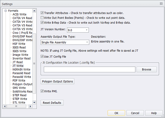 Using the right format is a great start, but it takes some fine tuning to get the best out of your CAD data translation workflow. When possible, careful analysis and testing needs to be done to achieve optimum translation from the customer’s format to the in-house format and back again (round-trip). There are several considerations; which version of a given format will you translate to? Do you want arcs and lines or hidden geometry to be translated in addition to the solid models? Does the situation call for a true assembly with referenced part files, or a single part assembly? If the customer is using JT, do they want you to use the JT Config file? (see figure at right).
The Argument for Having a Translation Solution
Whatever formats you choose to use, most companies will save time and protect design and manufacturing schedules by having a quality CAD translation and repair solution which will let them flexibly read and write a wide range of formats and versions, while having access to all applicable settings. Read more about how to select optimal formats in The CAD Format Ladder Part 1.
Check out IGES for more in-depth information about the IGES format.
We hope this article was helpful. Let us know if you have questions or comments by emailing us here: social@transmagic.com