by Brad Strong | Apr 28, 2016 | 3D Printing, Blog, CAD Translation, Polygonal Output, What's New
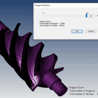
Polygon Reduction can have a Huge Impact on Productivity Polygon Reduction allows you to take any CAD or Polygonal model and reduce polygons for downstream uses such as 3D printing, Web parts libraries, animation, game development or other purposes. CAD, or Brep models: Brep (Boundary Representation) models are often incredibly detailed since they are often used to manufacture mechanical parts. Bringing this geometry into a 3d modeling and animation package like Maya, 3ds Max, Cinema 4D or Blender can be difficult due to all the polygons that are generated when the file is saved to a polygonal format. Polygon reduction eases this process immensely, allowing...
by Brad Strong | Apr 27, 2016 | Blog, CAD Translation, What's New
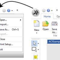
For basic translation and repair, TransMagic is pretty simple to use. Use ‘Open’ to open parts and assemblies, and Save As to save to the output format of your choice. But there are a lot of potential nuances to file translation and repair; where do you start? To answer that question, here are my top seven tips for new TransMagic users: Open and Import Open (see figure 1) is the simplest way to open any native or neutral format. In R11 and previous, the Open button had an upper and lower half (the bottom half was for ‘Import’), so it mattered which part of the button you clicked on. Import is useful if you want to import a file into...
by Brad Strong | Apr 26, 2016 | Blog, CAD Diagnostics, CAD Repair, CAD Translation, What's New
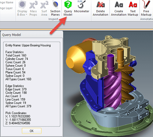
Quick Queries of Geometry and Graphical Feedback For this series, we’ve been looking into the diagnostic capabilitities of TransMagic. In this particular segment we look at two additional tools for geometry diagnosis that allow quick queries of geometry as well as graphical feedback. Click here to access earlier posts in this series, Diagnostic Tools for CAD Files Part 1 and Diagnostic Tools for CAD Files Part 2 and Diagnostic Tools for CAD Files Part 3. Query Model: The Query Model button is located on the Operations panel (see figure 1). This gives you the ability to query any model or body and returns the face and edge statistics, such as the total face...
by Brad Strong | Apr 20, 2016 | Blog, CAD Diagnostics, CAD Repair, CAD Translation, What's New
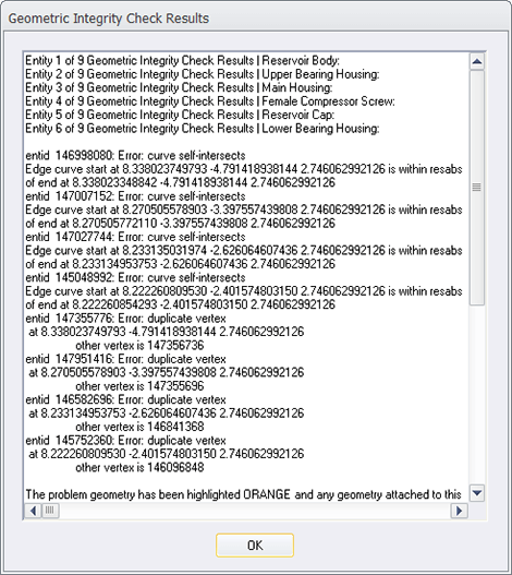
System Settings to Turn Off Repair and Turn On Diagnostics Note: This is the third article on Diagnostic Tools for CAD Files. This article focuses on how to turn off the normal repair feedback mechanism in TransMagic so that the diagnostic feedback becomes accessible. Click here to access earlier posts in this series, Diagnostic Tools for CAD Files Part 1 and Diagnostic Tools for CAD Files Part 2. In the early days of TransMagic, running any of the repair tools automatically generated a Geometric Integrity Check Results dialogue (see figure 1), which gave the user feedback about the integrity of each part in the assembly, and even drilled down to issues with...
by Brad Strong | Apr 12, 2016 | Blog, CAD Diagnostics, CAD Repair, CAD Translation, What's New
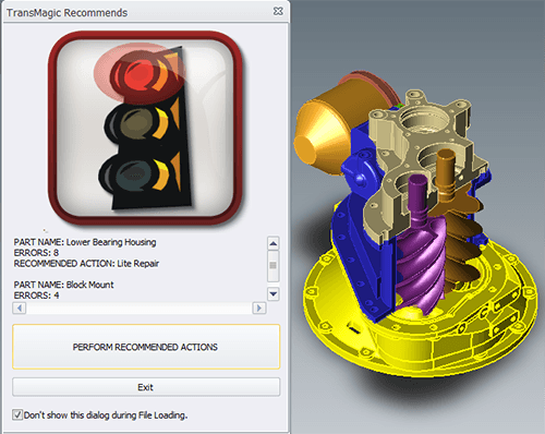
The Red Light and Error Feedback Note: This is the second article on Diagnostic Tools for CAD Files. This article focuses on what happens when you use the Auto Repair Wizard to repair a model and get the ‘red light’. Click here to access the first post in this series, Diagnostic Tools for CAD Files Part 1. The Red Light: Whereas the yellow light indicates open circuits where geometry is missing, the red light indicates more extreme problems such as bad vertices, bad edges, or self-intersections. Some of these problems can be fixed with Lite Repair, and some require Full Repair. Let’s look at a specific example (see figure 1). This SAT file has...
by Brad Strong | Apr 5, 2016 | Blog, CAD Diagnostics, CAD Repair, What's New
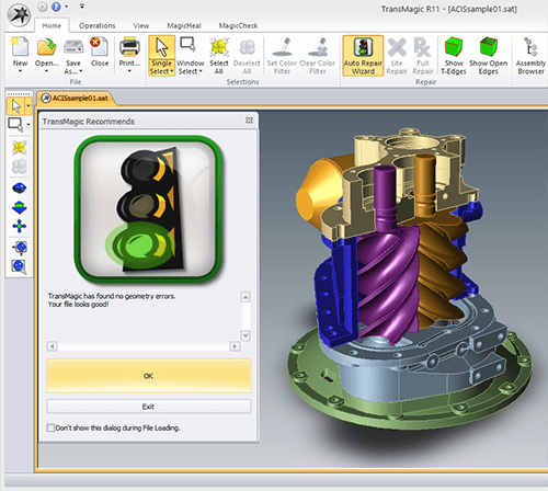
Using the Green Light as an Indicator of Quality Geometry Most TransMagic customers use TransMagic for viewing and quoting, translation between CAD formats, file repair or file comparison. Recently we found that some of our customers are using TransMagic’s features as diagnostic tools for CAD files to quickly determine the quality of their CAD files. If the file gets the ‘green light’ (see figure 1) and thus is found to be watertight, they know the CAD geometry is high-quality, and they send the geometry to design and engineering teams for further processing using a variety of CAD solutions. If the file gets the yellow or red light, it is not...


