
The IGES file has been the bane of the CAD/CAM/CAE world for years, yet it remains with us to this day. This article defines some of the problems with the IGES format. A follow-up article will propose some alternative formats which are better equipped to handle most 3D design data needs.
IGES stands for Initial Graphics Exchange Specification; it was first published in 1980 as a vendor-neutral file format to facilitate the transfer of information among different CAD systems, and though use has dropped in the last decade, IGES is still a widely used format in the manufacturing world. In fact, the 2013 3D Collaboration and Interoperability Report published by Jackson and Prawel noted that IGES was the second most commonly exchanged neutral CAD format right behind STEP, with 58% of companies choosing that over 3D PDF, Parasolids, ACIS or JT.
Here, then, are six reasons to avoid IGES files:
1. IGES is Old
The last official version of the IGES standard was in 1996. At this writing, that makes IGES 20 years old, an eternity in the CAD world. By comparison, the STEP standard was first released in 1994, and work continues on STEP to this day, just as it does with other useful neutral formats such as Parasolid, ACIS, SMS and JT.
2. IGES Geometry is not as ‘Information Rich’ as Solid Geometry
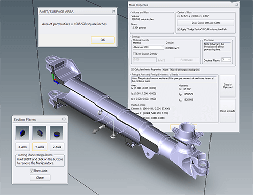
Figure 1 – Solids are much more information-rich than surfaces.
IGES models are surface files and as such have no mass properties information; though there is an IGES standard for solids (IGES-MSBO), it is rarely used. By way of contrast, solid models provide a wealth of information such as weight, volume, surface area, centroid and moments of inertia (see figure 1). They are also easily dimensioned, used to create orthographic views, and sectioned.
Solid models can also support MBD (Model-Based Definition) features such as PMI (Product and Manufacturing Information) which can clearly label GD&T (Geometric Dimensioning and Tolerancing) directly on the part, as well as associated dimensions and notes critical to the manufacturing of the part (see figure 1). Surfaces can do none of this.
3. Solid Models are Easier to Edit than Surfaces

Figure 2 – Opening an IGES file in Inventor.
IGES models, being surfaces, do not typically work well in CAD/CAM/CAE applications. Often it is desirable to make edits on an existing CAD model, but editing a surface is tricky business. It’s far easier to edit a solid model by selecting a face and adding a sketch or a placed feature. If you need the ability to edit features on the model (and that model was not built using your native CAD software), feature recognition can be employed to accurately assess and re-create part features – however, feature recognition tools need a watertight solid for input, and an IGES surface is not a watertight solid.
IGES into Inventor:
Figure 2 shows the result of importing a IGES surface model without gaps into Inventor vs importing a STEP file. The STEP import is the image on the top of the figure; notice that the file imported as a “Base” feature, meaning you can now build further features on it (or use feature recognition on it). The surface model with gaps is the image at the bottom of the figure; note that it comes in as what Inventor describes as a “Composite”. There is no ability to add features to this part, or perform feature recognition. A user may be able to resolve a good surface model into a solid using the CAD system’s modeling tools, but starting with a surface model ultimately ends up creating more work for the user.
IGES into SOLIDWORKS:
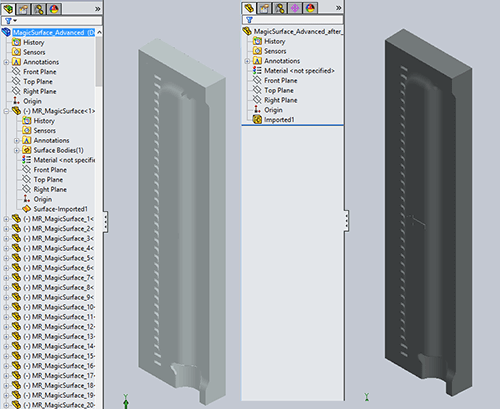
Figure 3 – Opening an IGES file in SOLIDWORKS.
Figure 3 is made of two screenshots; at left, how an imported IGES file with gaps appears in the feature tree, and at right, how an imported IGES file that is watertight appears in the feature tree. Some CAD systems can stitch IGES surface files without gaps into a solid model, but not all CAD or other downstream tools can do that. If your geometry comes in as a collection of surfaces, you’ll be forced to either:
- Use your native tools to try and stitch the surfaces into a solid model.
- Attempt to get your design or engineering task done using only the surfaces.
- Recreate the model from scratch.
- Request the file in a different format.
- Use tool like TransMagic to stitch your surfaces into solids
Since this is SOLIDWORKS we are talking about, a good policy would be to ask your customer for the format in either Parasolid or STEP. For more discussion on what format to use when, please see this article on the CAD Format Ladder.
Compounding the IGES problem is that the great majority of CAD users have little or no experience with surfaces; they are only familiar with the parametric / feature-based solid modeling tools in packages like Creo, SOLIDWORKS and Inventor, so when a thousand separate surfaces suddenly appear in their feature tree, they are lost.
4. IGES Cannot Carry MBD / PMI Data
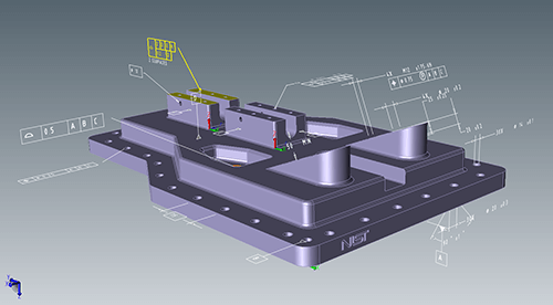
Figure 4 – A PMI example.
Model-Based Definition (MBD) is a rapidly expanding area wherein the details normally communicated with 2D drawings are attached to a 3D model, achieving the benefit of keeping all the project data in one place, and making the data easier to visualize in relation to the model.
All major CAD vendors now include PMI (Product and Manufacturing Information) creation tools in their software – this includes the capability to create dimensions, GD&T (Geometric Dimensioning and Tolerancing) and other notes that attach directly to the 3D model. This data can be read by viewers and translators such as TransMagic; STEP 242 is being built to handle PMI data, but IGES cannot carry this kind of information, mainly because PMI appeared long after IGES was established and development had ended.
In figure 4, you can see the GD&T portion of the PMI in white text; one callout is yellow because it is currently being selected. Selecting PMI text will in many cases highlight the associated geometry on the part, so that it is clear what feature that particular note goes to. This kind of visual association makes design, engineering and manufacturing more exacting and decreases the risk of misunderstanding critical data.
Writing PMI out to IGES when necessary: It is worth mentioning here however that if you absolutely need PMI in the IGES format, TransMagic Pro and Expert have the ability to write PMI out as ‘wires’ or ‘edges’ to virtually all CAD formats, even IGES. Such PMI is not ‘intelligent’ or associated to the part, but it will give you the readable entities you need to see in the way of GD&T, dimensions and notes. If you want to enable this capability, just enable the setting called ‘Write PMI Out To Wires’ in the Settings interface.
5. Downstream Applications Prefer Solid Models
Almost all downstream CAD applications require or prefer solid models as input. A partial list includes:
- Machining
- FEA or other analysis
- 3D printing
- Part and assembly visualization
- Photorealistic rendering (for product design reviews, marketing and sales)
- Ability to automatically create exploded assembly drawings for bills of materials and assembly diagrams
- Functional assembly movement simulations for use cases as well as training manuals
6. IGES files often need to be repaired
Since IGES files are almost always surfaces, and since surfaces are most commonly a collection of bodies that happen to sit next to each other yet know nothing about each other, it’s common that IGES files often require time-consuming repair or complete remodeling – and at minimum, they need to be stitched into a solid model. As the 2013 State of 3D Collaboration and Interoperability Report noted, nearly 50% of engineers spend over four hours a week fixing design data; it is easy to see how so much time spent repairing models could throw off the production schedule.
Generally speaking, anyone using IGES today should be doing so because they have no other options. Those who must deal with IGES files should make sure they have the in-house tools to make geometry repairs (such as removing duplicate vertices, zero area faces, and extending and reintersecting faces) and are able to sew the various surfaces into a watertight solid. Sometimes an IGES surface is missing one or more faces – in this case, a tool like TransMagic MagicHeal has the ability to interactively or automatically cover missing faces. Additionally, users should have the tools to translate watertight solids into more viable formats, such as Parasolid, SAT, JT, CATIA, STEP, etc. One such tool that covers all these contingencies is TransMagic EXPERT (www.transmagic.com).
Related Articles
In another post, we discuss 3 alternatives to IGES.
Our recent IGES post goes into the history of IGES as a ground-breaking universal CAD format, and a wider range of issues that eventually resulted in the STEP format.
Check out IGES vs STEP to see the pros and cons of these two mainstay neutral formats.