The CAD Format Ladder
The CAD Format Ladder can help you optimize data exchange with your customer or supplier. At TransMagic we often deal with CAD file translation and repair issues. These issues can be minimized by using this rule of thumb:
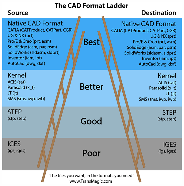
“When sending out CAD data, or receiving CAD data, go as high up on the format ladder as possible.”
Your best results: Your best results will come from sending customers or suppliers a format that is as high up on the format ladder as they can read or open. Likewise, you’ll want them to send back data in a format that is as high up on the ladder as you can read. Why is this? Because the higher you go on the format ladder, the better quality the data is – and conversely, the lowest point you go on the format ladder becomes the weakest link in the file exchange. The weakest link can be the format that ends up generating sliver faces other artifacts that may require repair and in some cases may need to be completely remodeled.
Native, Kernel, STEP and then IGES
As the CAD Format Ladder suggests, your optimal format is always the native CAD format (such as CATPart, SLDPRT, DWG, etc.), followed by the kernel format (such as Parasolid, ACIS, etc.), followed by STEP and then IGES. Read more about kernel formats here.
Using the CAD Format Ladder
The Goal of the Translation: The Goal of the Translation should be to generate the best geometry possible, preferably watertight solids that include any PMI information attached to the model.
Watertight Solids: Watertight solids allow you to perform additional edits on the imported geometry in your CAD system, as well as to create logical mate relationships. If the geometry is not watertight, it is probably surface geometry – which can import into CAD applications like SOLIDWORKS as hundreds or even thousands of unconnected and nearly useless surfaces.
High-Quality Geometry: It is not enough that the geometry be watertight, but you really want it to be free of artifacts such as sliver faces, zero-area faces, duplicate vertices, and splines. This is because these artifacts can make translation into your CAD system difficult, as well as hindering downstream applications such as feature recognition, machining, and FEA. Sometimes translated geometry is high-quality, but often it needs to be repaired to remove artifacts and to extend and reintersect edges.
PMI: If your part or assembly contains PMI (Product Manufacturing Information), you’ll want access to that as well; PMI refers to data such as GD&T, dimensions, and notes which are attached to the solid model. PMI data is often readable in a native format, but will be lost in a neutral format unless you convert it to Geometric PMI (arcs and edges).
We hope that you will find this post helpful in your CAD translation challenges. If you’d like to jump right to the second post on this subject, find The CAD Format Ladder Part 2 here. If you have questions or comments, please let us know at social@transmagic.com.
Related Articles
To see all the formats TransMagic can open and write to, visit our CAD Formats page.
To take advantage of Geometric Modeling Kernels, it helps to know which kernels underlie which CAD applications; here’s a helpful listing. Which Geometric Modeling Kernel?
Why is IGES at the bottom of the list? Read more about IGES in these posts; IGES, and IGES vs STEP.