This article is in collaboration with Dimensional Control Systems, authored by Ben Reese, DCS Marketing, and Norm Crawford, Model Based Definition Specialist.
Part 2 of the MBD Series with Norm Crawford – understanding what MBD is and the value of implementing MBD
The second part of the DCS series of Model Based Definition (MBD) articles, Norm Crawford, an expert in MBD implementation, discusses MBD with us at DCS, and shares his experiences in both successes and failures in Model Based Definition.
Read the Other Parts:
- Understanding Model Based Definition with an Expert in GD&T
- What is Model Based Definition MBD? Why Implement Model Based Definition?
- The Largest Barrier and Common Mistakes in Implementing Model Based Definition
- Adopting GD&T – Getting Started with GD&T in Model Based Definition
- Academic and Generational Influence on Model Based Definition Adoption
From Norm Crawford – https://www.linkedin.com/in/normcrawford/
Model Based Definition – MBD – Defined
People want that one clear and concise definition.
Succinctly, MBD is a computerized design or CAD model that over the years has had lots of crazy terms. But essentially it is when the 3D solid model is the master and contains all the information necessary to produce a part that you would often find on a 2D drawing.
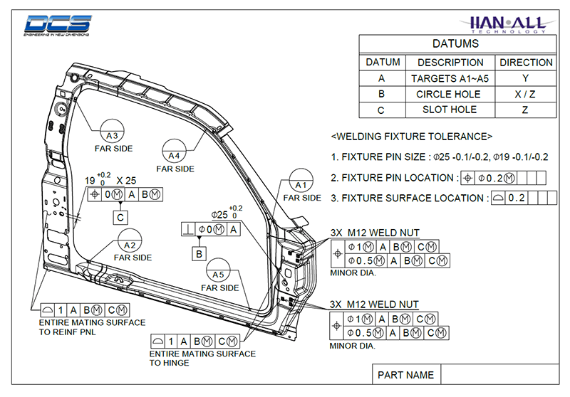
2D drawings are the traditional method of documenting part designs and GD&T
MBD places all of the design information on the CAD model, reducing or removing the need for 2D drawings
You can get into arguments that all the information to produce a part isn’t on the 2d drawings, as there are also other documents incorporating the manufacturing process, suppliers, tooling, equipment, assembly lines and inspection plans, which gets more into Model Based Enterprise (MBE)
MBD is specifically around the piece part geometric Definition and the tolerances permitted to meet those Geometric Definitions.
Why Implement Model Based Definition MBD?
There is a big separation between MBD and MBE, which is a common mistake that causes confusion and cultural issues within a company. So, if we stick with MBD, it is simply way more efficient and reliable to produce the PMI or annotations on the CAD model than it is to transfer to a drawing format that often requires a different environment in the CAD system often requiring a different set of menus. So, MBD PMI is just faster and it is simply more clear; easier to visualize and understand.
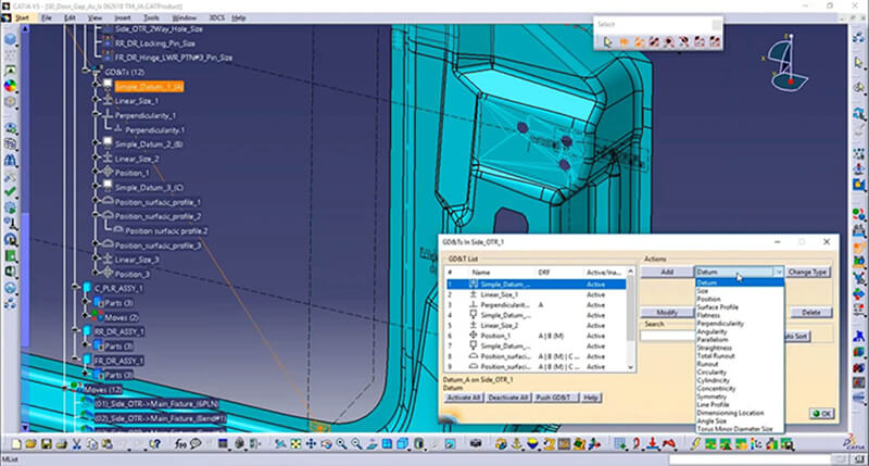
Easier to understand when the information is in context and on a 3D representation
When reading blue prints – we have to go back to reading various section and detail views often scattered on multi-sheet drawings. Finding the details of any one feature is often unclear especially when sections can become very complex zig zag sections, sometimes defined on separate sheets and then sometimes rotated by some angle all in the intent to clarify what is going on with the section. With the technology in MBD far fewer section or detail views are needed and even if such views are created, they are just easier to visualize, understand and read in a dynamic 3D model. Each feature involved with such views is much more identifiable and on many CAD systems, the section detail can be echoed on and off for additional clarification.
Do companies understand why they are doing this or just following the trend?
Companies get a high level sense that there is some value. So, any company trying to implement MBD usually has some objectives in mind. Typically, they are looking for those efficiencies in part definition and collaboration during initial development. Many companies that have initiated MBD practices are reporting that annotating in 3D is faster than 2D. When they run pilot projects, they are looking to see if they can save man hours in producing their final part definition document.
Most companies recognize they want that benefit. Now, whether they get that benefit is another issue.
Using MBD to Improve Version Control
The 3D model is infinitely better at version control. Companies, for years and years, have struggled with how to keep their drawings directly associated to their models. Thus, enter the PDM systems (and now PKM, PLM) in order to keep that connectivity going on. However, 2D pdfs of CAD drawings get pulled down from the system and often all stand alone and unconnected once pulled down from their container.
If I’m working on a 3D model, in the attributes of most 3D models, the way a CAD system will produce an MBD, is the inbuilt revision control within the metadata on the model itself so that I can click on the model and know what version the model is. Whatever PMI is on that model is directly associated to that model. Whereas if I need to review a standalone 2D PDF or hard copy, I have to do all sorts of checking on whatever CAD model I ‘think’ is associated with that PDF before I can continue to work through whatever information I am looking for. This takes a lot of extra time and prone to many human errors. And the revision control box on the 2D drawing is not always up to date. So, that is very difficult to rely on. People say well that means you could be still working on revision B and there could be a revision C released out there. Yeah, that’s true, but at least I know that I’m working with version B and the tolerances associated to version B.
If I am not told about or otherwise notified about version C, that’s another issue. But at least I know what I have in my hands. In many PDM or other document control systems, the model can be at revision C and the drawing still at revision B until someone actually takes the extra time and effort to go into the separate drawing world of the CAD system, update the drawing, and then file it away at the new revision level. Many may say this is all handled automatically. Trust me. I have been involved with PDM, PLM, and PKM systems since before they were invented. Keeping separate, although associated, 2D drawings updated and at the proper revision levels along with the solid model remains a royal pain to keep synchronized. Don’t believe me? Ask any supplier dealing with an OEM having drawings that do not match the model.
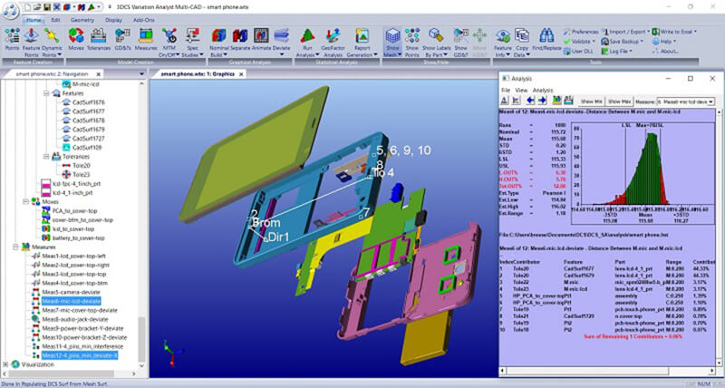
Is this up to date? How do I know?
It follows that the version will also be noted in reports and outputs, making downstream users aware of the version and related information. MBE can automate all of that, making it much cleaner rather than having to reference something in the text body of a report. And any such report can easily be associated to just the MBD CAD model and not deal with the additional linkage of an out of date drawing.
The revision control, it is much more fluid in MBD because users are only updating the CAD model. They are not continually updating both the CAD model and the associated drawings. And as I previously said, it is very common that the drawings are not continually updated. If you have a 2D drawing associated with a CAD model, and you’re working on the CAD model taking it from revision C to revision D and even if you have a good system that associates the 2D drawing, when you open the 2D drawing you can have entire views missing. Detail dimensions sometimes disappear making it difficult to realize that they did. Granted some dimensions may change color or font notifying a user of a change, whatever that is when looking at only a 2D view. You get all kinds of notifications telling you that the drawing is out of date, but it is still out of date. Drawings simply do not get updated because it is an extra step to go into the drawing environment to update the drawing. I always hated having to do that.
With MBD the 3D PMI may go out of date, and a good cad system will notify you the PMI is out of date, but it is right there in front of you on the model and so it can be quickly realized and instantly corrected on the fly. So, the information and PMI stay up to date much more easily in MBD. There are of course modeling techniques so that the PMI automatically stays up to date without any correction. The same is true for good associated drawings. But again, the user doesn’t know if the dimensions correctly updated based on the modeling techniques or not until the user switches over to that 2D drawing environment. And does anybody think users are going to do that with every model change? No way! It’s a hassle.
All core TransMagic products allow you to read PMI and extract PMI to 3D PDF. Try the evaluation now!