 STEP to STL is a popular translation workflow. Let’s look at what this entails, and best practices.
STEP
STEP is a CAD Brep format developed in the 1980s as a successor to IGES, and like IGES is a neutral CAD format. STEP files can vary in quality depending on what translator was used to generate them or read them. So the first thing to recognize about the STEP part of this equation is that there may be a better format to start off with.
STL
STL, which stands for Stereolithography, is a polygonal, faceted, Visrep (Visual Representation) format which is used to approximate CAD and other geometry. STL is primarily used for Additive Manufacturing (also known as 3D printing) and Finite Element Analysis (FEA), but can also be used for machining. For the purposes of this discussion we will focus on additive manufacturing applications. The important thing with STL output is starting with a watertight solid model, and then getting the tesselation optimal for your purposes.
Bypassing STEP
If you can get your hands on the original CAD file, whether it is CATIA, NX, Creo, SOLIDWORKS, Solid Edge, Inventor, AutoCAD, Parasolid, ACIS, SMLib geometric solid modeling kernels, you are better off bypassing STEP and translating directly from the native or kernel format to STL. There is a hierarchy of which formats have the best information, and the native CAD format is always the best; the geometric modeling kernel format is next, and STEP is third. Read more about this hierarchy, known as the CAD Format Ladder, here.
If STEP is all you have and all you can get, then by all means, at least use the best STEP translator you can get to read it, because, as we often state at TransMagic, a STEP translator can hurt you twice – when the file is being written, and when it is being read. A bad STEP translator on either side of this equation can still generate geometric problems.
Start with a Watertight Solid
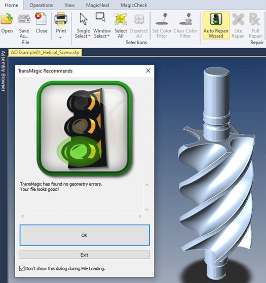 You want to start with a good quality model because if there are any missing faces or bad geometry, you will not have a watertight model, and all 3D printers require a watertight model.
‘Watertight’ means that if the model were filled with water, no water would leak out; no faces are missing, there are no gaps between edges. If a face is missing, or there is a gap between any edges, the model is not watertight; and that’s one reason why starting with the highest quality CAD file you can get your hands on is important.
If you have a STEP model and it has issues, you can run repair operations on it to reextend boudaries and intersections in order to heal gaps. You may also be able to use CAD repair tools to replace missing or damaged faces. Then you can restitch the CAD model faces together and proceed to converting the model to STL.
STL Output Settings
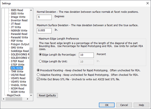 When you write to STL you have a great deal of control over how the model is faceted. As shown in the figure at right, you can tune output for Normal Deviation, Maximum Surface Deviation, Maximum Edge Length Preference, control over Edge Length and whether you are using Procedural or Adaptive Faceting.
All four settings are going to affect mesh density in different ways, and increasing mesh density is often imporant to achieve smoother curves on 3D models; however, since high mesh density can make files hard to manage in terms of file size and complexity, it’s best to add mesh density in the right places, rather than blindly or all over.
Normal Deviation
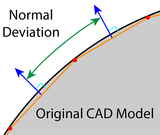 Normal Deviation is the maximum deviation between surface normals at facet node positions. This is an angular value. The default is 5 degrees, meaning that a facet normal has to be within 5 degrees of the neighboring facet normal at the facet node. Normals are imaginary lines perpendicular to any given surface.
In the figure at right, the gray sphere represents the original CAD model. The faceted polygons are represented by the orange lines, and the red nodes mark where the nodes connect. You will note that the orange polygon faceting is inclusive, or generated inside of the original model surface. Facet surface normals are shown as blue arrows. The green arrow shows the angle between facet normals.
Maximum Surface Deviation
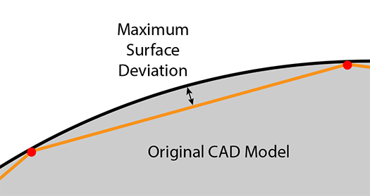 Maximum Surface Deviation is the maximum deviation between a facet and the original CAD surface (the true surface).
In the figure at right, the original CAD model surface is shown in black, and the faceted STL model is shown in orange. The maximum distance between the facet and the original CAD model surface is the maximum surface deviation.
Whether you are going STEP to STL, or from any CAD format to any polygonal format, this setting is a good one to tune if you generally want to make the STL model look as simlar to the original CAD model as possible.
The smaller you set this value, the more closely the STL model will resemble the original STEP CAD file, but, the resulting mesh will also be that much bigger.
Maximum Edge Length Preference
 Maximum Edge Length Preference is either controlled by Edge Length By Percentage or Edge Length By Unit.
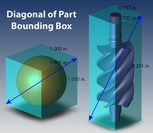
Percentage means it is based on the length of the diagonal of the Bounding Box. If a part is 2 x 2 x 6, the diagonal of the bounding box is going to be about 6.63 long. If the default of Edge Length By Percentage is used, that means no facet edge will be longer than 10% of 6.63 inches, or 0.66 inches.
At right you can see two examples of bounding box diagonals. The benefit of this setting is that it gives you a hard and fast way to control facet sizes, but as you’ll see in an example below, it can be somewhat ‘brute force’ and create facet edges in planar areas which do not aid in describing the geometry, thus increasing file size and complexity unnecessarily.
Procedural Faceting vs Adaptive Faceting
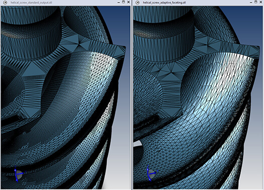 Procedural Faceting will facet surfaces based on their procedural definition (cylinders, cones, tori, spheres) where possible, which is more accurate, and is also faster than adaptive faceting. The accompanying image at left is an example of procedural faceting.
Adaptive Faceting places facets where needed, based on maximum surface deviation. Higher curvature areas get a greater number of facets, lower curvature areas get fewer facets, with a goal to attaining a uniform triangle sizing. The accompanying image at right is an example of adaptive faceting; you can see that it is less regular and gridded than the procedural example.
Adaptive faceting is processor intensive, and is best used for generating Finite Element Analysis (FEA) mesh geometry.
Everything else being equal, procedural faceting will produce more polygons and a larger file. The procedural example on the left is 15MB, the adaptive faceting example on the right is just under 4MB.
Test Drive TransMagic
The screen captures in this article, and all of the associated information was generated with TransMagic. If you are not already a TransMagic customer, there is a free evaluation version you can try with your own CAD data.
Related Articles
The Polygon Reduction Slider is an intuitive way to interactively reduce polygons. Learn more about Polygon Reduction here.
Pre-Processing for Polygon Reduction
3D Printers Under $4000 Compared for Industrial Usage