Eleven Techniques to Optimize 3D Printing CAD Files
3D printing and additive manufacturing processes are increasingly being used in to achieve quick turnaround on prototypes and to generate complex models cost effectively in low volume. Preparation of the geometry is the key to getting optimum results with 3D printing. The following techniques can shave hours off of the process of 3D printing CAD files.
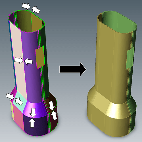
Figure 1 – Surface Stitching models watertight.
1. Watertight Models
Designs used for 3D printing need to be watertight solid models. 3D printers pre-process models into very thin horizontal slices of the part. Watertight geometry is necessary for the preprocessing step to avoid errors. Often, surfaces can be stitched into watertight solids instantly, since the repair tools are automatic upon opening a CAD file. Repairing a 3D model is best done while it is in the CAD format, prior to converting the file to the STL format used by 3D printers. All TransMagic core products (SuperView, Pro and Expert) come with Lite Repair, which allows the majority of surface models to be stitched solid. For models with more extreme geometry problems and errors, TransMagic’s MagicHeal has Full Repair and Magic Surface, with the power to close gaps, fix self-intersections and replace missing faces with minimal effort. See figure 1.
Figure 2 – Polygon Reduction in Action
2. Polygon Reduction
CAD files are typically huge when converted to polygon meshes for 3D printing. The Polygon Reduction tool makes it as easy as moving a slider to intuitively adjust the density of the polygon mesh; you also have a polygon and vertex readout to help you assess how the model will look (see figure 2). Polygon Reduction can be used independently of Polygon Optimization, which is covered in the next bullet. The default density of the CAD model is fairly high, but there are settings that will allow you to achieve a nearly infinite density if so desired; for further information, see the full article on Polygon Reduction here.
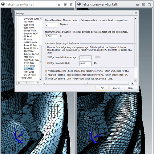
Figure 3 – STL Mesh Optimization allows for different approaches.
3. STL Mesh Optimization
Successful 3D printing or additive manufacturing demands a high-quality STL mesh. 3D printing has many different uses, such as checking fit, function, ergonomics, aesthetics and more. Quality constraints can vary between a prototype and a finished part; often, at the prototype stage, you just want to get a sense of the part and are not so concerned about material finish. A fine mesh will help avoid ‘flat’ faces on curved surfaces to optimize aesthetics and functional designs. Angle control and Chordal deviation controls allow the designer or engineer to determine exactly how closely the STL mesh will follow the original CAD model geometry. Adjusting ‘Edge Length by Percentage’ or ‘Edge Length by Unit’ can give a wide variety of results, depending on the specific need. All TransMagic core products allow the user to optimize STL faceting, enabling nearly infinite mesh control and density (see figure 3).
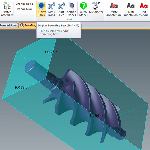
Figure 4 – Part or Assembly Envelopes can be generated by a Bounding Box.
4. Part or Assembly Envelope
It is important to know if the part will fit within the build envelope. All 3D printers have a finite build envelope which the part must fit into. All TransMagic products offer a one-click Bounding Box tool that instantly builds the minimum size box, in X, Y, and Z dimensions, that will encompass the part. It is also possible to adjust the orientation of the CAD model with Precise Positioning tools so that the bounding box orients differently (see separate bullet on Precise Positioning below). If the bounding box dimensions are too big to fit within the 3d printer area, the parts can be scaled (Scaling is covered later in a separate bullet). The Bounding Box dimensions show up automatically for easy reference, Bounding Box precision is adjustable, and the Bounding Box can be moved away from the part if so desired (see figure 4).
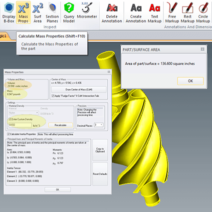
Figure 5 – Mass Properties can provide Volume and other information.
5. Mass Properties Calculation
Whether you are dealing with a part or an assembly, it helps to know how much material the geometry will require. Using Mass Properties calculations, you can input the material density to determine the weight of the part as well as the volume, in cubic inches or cubic millimeters. Materials properties are currently being read from most 3D CAD systems including Creo, CATIA and SOLIDWORKS, and these values are used to generate volume calculations. Other part data displayed are center of gravity and inertial moments (see figure 5). Draw Center of Mass will generate three workplanes which describe the centroid of the part or assembly for easy visualization. Results can be copied to the clipboard for easy access in other applications. You also have access to Surface Area calculations, measurement tools such as the micrometer, and the ability to dimension CAD geometry for estimates and quotes.
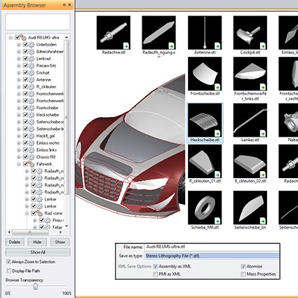
Figure 6 – Atomization separates parts from assemblies for 3D printing.
6. Separating or isolating parts from an assembly
Sometimes it may be helpful create discrete STL files of all of the parts in a multi-part assembly. TransMagic offers a feature, called Atomize, which does exactly that. An entire assembly can be broken into individual STL part files, so that each part can be printed separately. Atomize works whether the file is true assembly, or a monolithic assembly made up of solid bodies. With a single setting, TransMagic can make the process happen automatically – simply check the ‘Atomize’ checkbox when saving the file. TransMagic’s Atomize feature will automatically break the entire assembly into individual part files in any supported format. If you have hundreds of these assembly files and would like to automatically atomize them without having to open them up, the MagicBatch add-on will allow you to turn hundreds of full assemblies into separate part files in minutes (see figure 6). Figure 5 – TransMagic’s Atomize feature allows you to isolate parts from assemblies automatically.
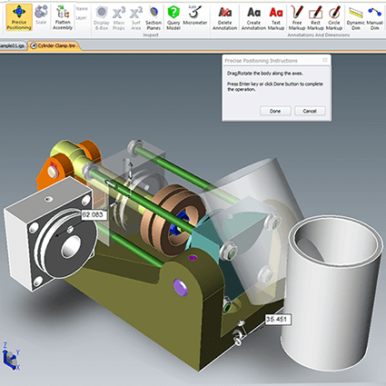
Figure 7 – Assembly Mockup – Parts can be imported and repositioned.
7. Assembly Mock Ups and Precise Positioning
Printing 3D working assemblies can require the ability to import and position components. TransMagic lets you mock up new assembly designs from parts from any major 3D CAD format in the world. This means you could create a new assembly with disparate parts from CATIA, NX, Creo, SolidEdge, SolidWorks, Inventor, AutoCAD, Parasolid, ACIS, SMS, STEP and even IGES, and then move the parts to the orientation and position you desire. Save out STL geometry of the assembly and send to the 3D printer as one assembly file or as separate parts. Change part colors as necessary. Parts can be aligned in many ways including planar alignment, concentricity, parallel edges, linear transforms, rotational transforms, 3-point transforms and freeform transforms, and linear and angular movements can be done either intuitively or by using precise values (see figure 7).
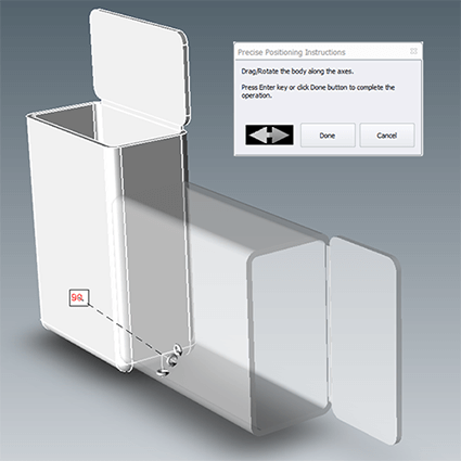
Figure 8 – Part orientation can improve 3D printing results.
8. Part Orientation Optimization
Part orientation can be critical in 3D printing. For example, inserts should be positioned in such a way that the printing process can continue once the insert has been added to the part so that the insert will not get in the way of the printing tip. Living hinges should be built so that they are part of a series of contours connected to the main body of the part; failure to do this will result in a much weaker part. In the example in figure 8, the original orientation will create a living hinge that is prone to breakage, with a single layer of PLA or ABS plastic holding it in place; the ghosted orientation will, on the other hand, provide dozens of layers of connection along the length of the hinge, ensuring much better performance. Precise Positioning allows the user to rotate the part into an optimal angular orientation prior to optimizing and writing the STL file.
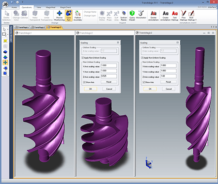
Figure 9 – Models can be scaled to allow for mold shrinkage.
9. Part Scaling
Sometimes the prototype part needs to be smaller or larger than designed; simply enter the decimal value to scale by. For example to scale an object to half size, enter 0.5. If the full-sized prototype will not fit within the 3D printer’s build size, simply scale it down. If your 3D print is to be used for mold development, you may want to scale the mold size accordingly to compensate for material shrinkage. Another reason to scale is if you are trying to optimize the overall part height so that it can be produced with near-perfect accuracy in the z-axis. All TransMagic core products offer Part Scaling to accommodate these needs and scale geometry. TransMagic EXPERT provides advanced features to scale parts non-uniformly (see figure 9).

Figure 10 – Part Simplification can remove holes or other features.
10. Part Simplification
Sometimes parts need to be simplified by removing features before printing. It could be that the CAD model has undesirable features, or it may be necessary to remove holes from the model, so they can be placed later with high precision in a post-print machining process; this process is as simple as selecting the inside of the hole and automatically resurfacing the hole openings. If inserts or other hardware need to be applied to the part, it can be helpful to have tools to modify model geometry as necessary. The MagicHeal Add-on offers an advanced toolset to that can be used to remove features such as holes and bosses, giving you more flexibility in design and manufacturing situations. MagicHeal also offers advanced repair features such as Full Repair and Magic Surface (see figure 10).
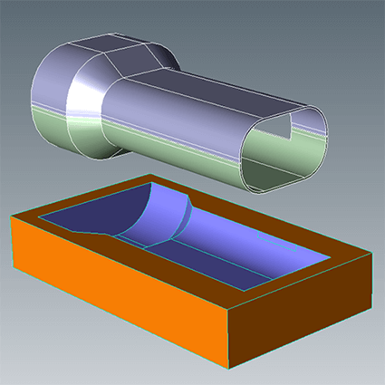
Figure 11 – Boolean subtractions can create mold cavities.
11. Unite or subtract geometric shapes
TransMagic can create molds by subtracting one 3D shape from a block and then scaling the new mold to allow for shrinkage factors. If you want to print a package design for a new product (part or assembly), the product design assembly can first be united into a single part, subtracted from a package block, then scaled to allow for shrinkage or loose fitting. TransMagic can create a perfect negative for the finished assembly packaging. Or you may want to subtract geometry from a thick wall in order to create a sparse or honeycomb fill, which will shave part material, weight, and print time from your design. TransMagic’s Boolean Unite and Subtract functionality allows you to A) unite several parts or an entire assembly into a single part, and B) use parts and blocks as bodies to subtract geometry from other parts (see figure 11).