 Pre-processing for polygon reduction is possible using polygon facet resolution settings. Since the Polygon Reduction tool starts with a default facet density, it can sometimes be useful to adjust that pre-set facet density to a higher value. More information about the Polygon Reduction tool can be found here.
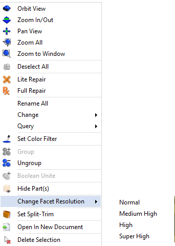
Figure 1 – Change Facet Resolution lets you adjust underlying facet density.
Change Facet Resolution
Starting with a sample CAD component, you can select the model with the Single Select tool, or just “Select All”, and right click to get the Change Facet Resolution options (see figure 1):
- Normal: The lowest resolution option, approximately 27 segments on a cylinder or hole.
- Medium High: Slightly higher than normal, approximately 36 segments on a cylinder or hole.
- High: Roughly double the resolution of Medium High, approximately 72 segments on a cylinder or hole.
- Super High: The highest resolution Change Facet Resolution is capable of, approximately 512 segments on a cylinder or hole.
Examples of various facet resolutions are shown in figure 2.
Triangulated Display Mode
To see facets clearly, choose Triangulated Display Mode from the Rendering section of the View toolbar.
Redraw
In the current build of TransMagic there is a small bug where the faceting resolution does not update unless you select the geometry and enter Control + R (to Redraw the screen), or press the Redraw View button located on the Rendering portion of the View toolbar.
A Better Starting Point
It is important to note that adjusting facet resolution is only useful for pre-setting the facet resolution prior to invoking the Polygon Reduction tool. One reason for adjusting facet resolution is to get a different visual result when you render an image on the screen. Raising the facet resolution of the CAD file can also give you a better starting point for the polygon reduction process, and different starting facet resolutions will give different polygon reduction results.
Once the Polygon Reduction tool has been invoked, your file will be converted to a polygonal model, and you can then save out to any polygonal format you choose without experiencing any additional change to polygons. Read more about the Polygon Reduction tool here.
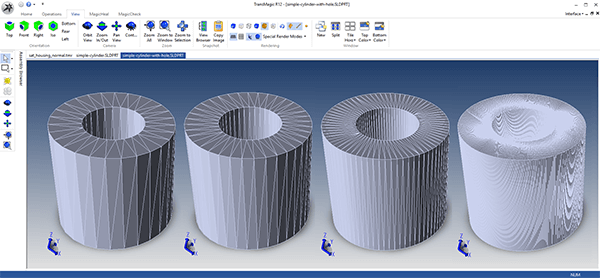
Figure 2 – CAD Facet Resolution Options
Here’s an example of what each facet resolution would look like with a simple cylinder and hole geometry (left to right – normal, medium high, high, super high). Note that ‘super high’ facet resolution is extremely dense and will require more RAM to generate and display, especially for larger models.
Saving a Polygonal Model out to a Polygonal Format
Once you have used the Polygon Reduction tool, you now have a polygonal model; if you save this model out to any polygonal format, your facet resolution will not change.
Saving a CAD model out to a Polygonal Format
Just to be clear, if at any time you save a CAD model out to a polygonal format, you will be automatically invoking the settings for that format (Settings > Formats > STL Write or Settings > Formats > Polygon Output). Using this technique, you can fine-tune how the model is faceted via normal deviation, surface deviation and max edge length; values can be set to achieve nearly infinite facet density if so desired. For STL, polygon options are found in STL Write. All other polygonal formats use settings found in Settings > Polygon Output.
If you haven’t tried Polygon Reduction yet, give it a try – find it on the Operations menu; you’ll need to open a model before the menu will come up. And if you haven’t tried TransMagic yet, there is a free TransMagic SUPERVIEW demo, which comes loaded with MagicHeal (for repairs) and MagicCheck (for comparisons). To try the TransMagic Eval, CLICK HERE.
We hope this article has been useful to you. If you have any questions or comments, please send them to social@transmagic.com.