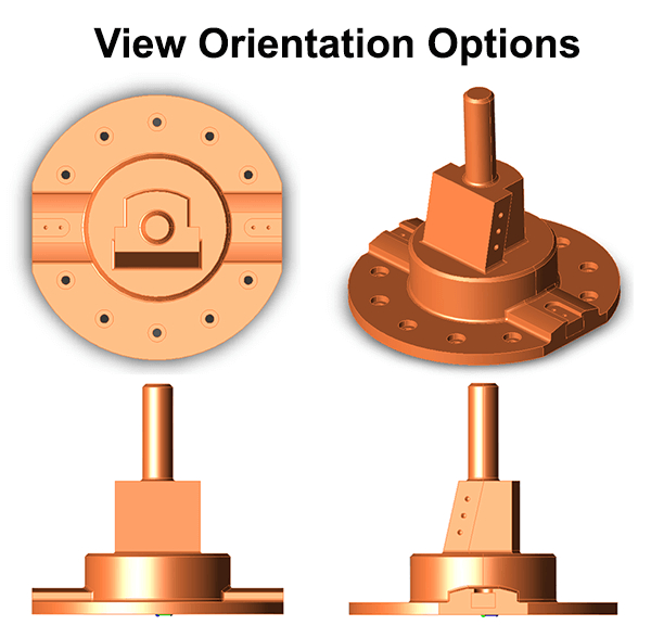
 This article and video will describe how to best use the View Orientation controls for TransMagic.
On the surface, the TransMagic View Orientation tools work just as any other view orientation tool you might have experienced, but there is the added capability to get almost any view you can imagine by “setting up” your view orientation before you invoke it.
This process involves using the orbit tool to get the orientation close to how you want it, then clicking one of the view orientation buttons to lock in the desired view.
Below is a video showing the view orientation process, followed by text and screenshots.
Video – View Orientation Options
Text – View Orientation Options
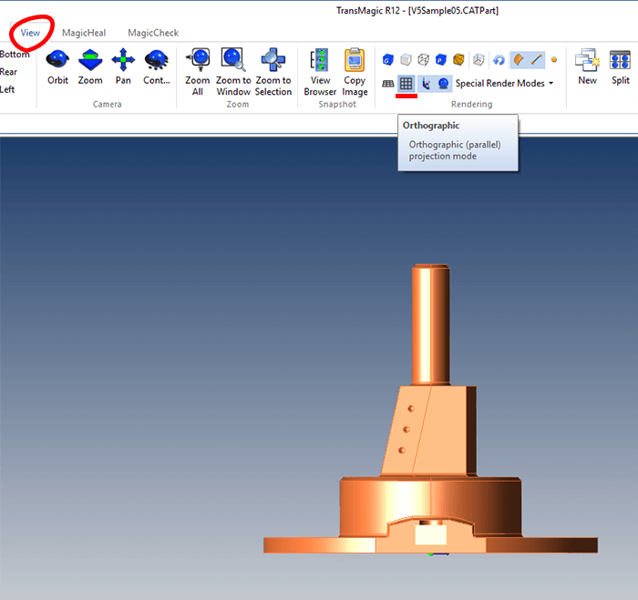
1. In Figure 1 (below), View > Orthographic is being selected; this generates true orthographic views (rather than perspective views) when you select different default view orientations.
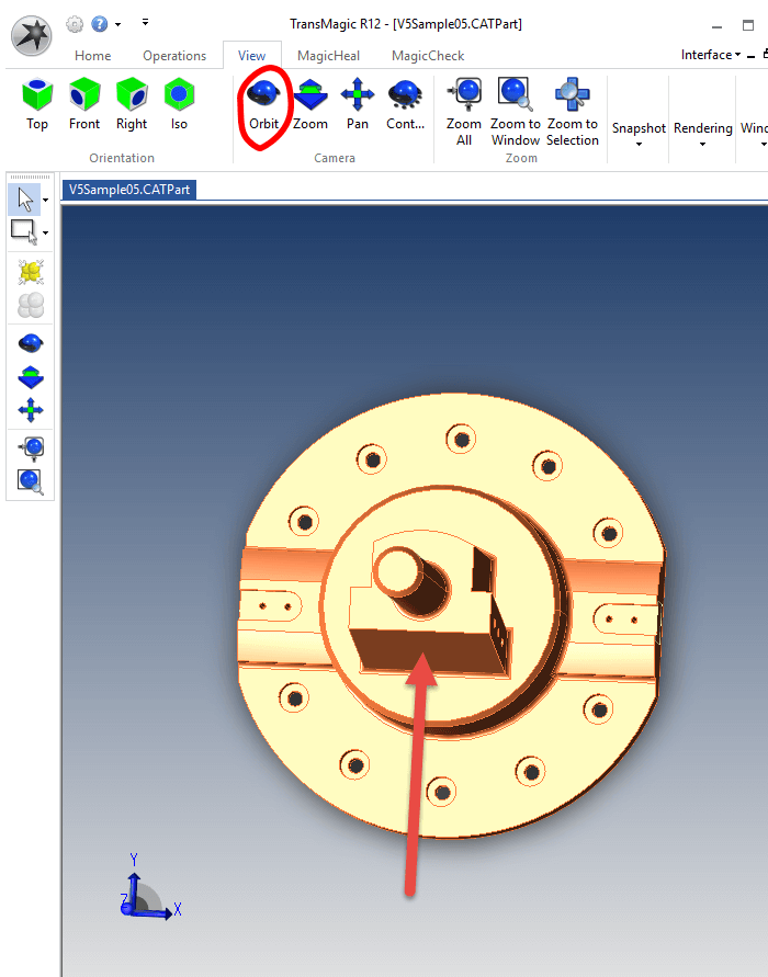
2. Figure 2 (below) demonstrates using the Orientation tool to rotate the view of the model until it is close to what you want for a Top view. If you can get within about 10 degrees of the desired view and then click the Top View button, TransMagic will do the rest. In this case the goal is to have the flat face (shown with the arrow) pointing down.
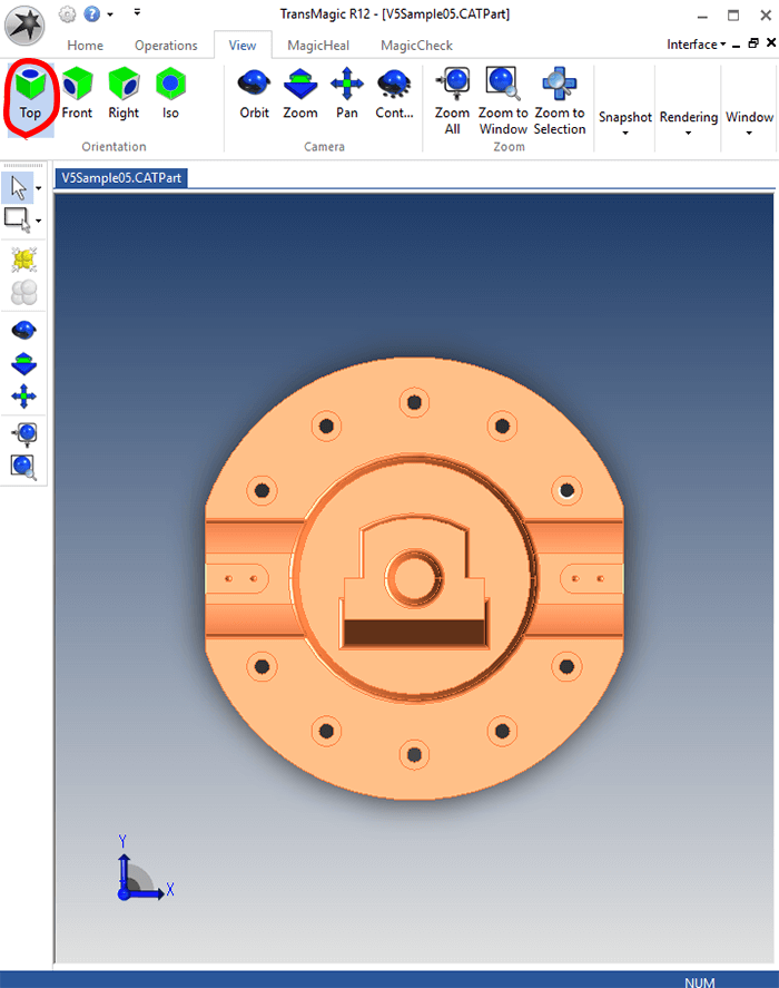
3. Figure 3 (below) shows what happens when the View > Orientation > Top button is pressed; TransMagic finishes the work and generates the desired orientation and rotation of the part; note that the flat face is pointing down.
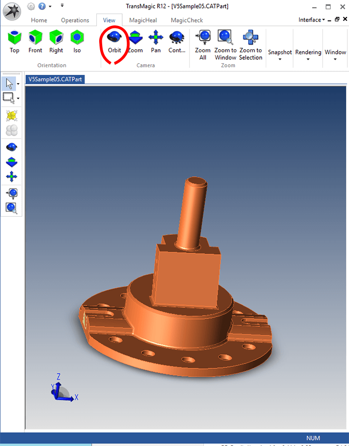
4. Figure 4 (below) shows the orientation setup for a custom Front view. Just get the view close to how you want it, and when you click the Right button, TransMagic will do the rest.
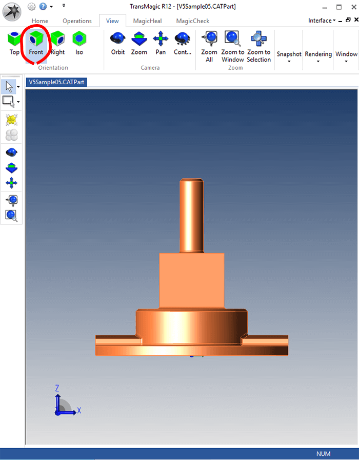
5. Figure 5 (below) shows the result when the Front view orientation button is clicked.
Keep in mind that there are several View > Rendering options, and you do have the ability to change background colors, in order to generate the view you need for your communication and documentation processes.

