 Boeing Spec D6-51991 Part 2 addresses another critical aspect of the Boeing D651991 spec: Translations.
For our recent articles on aerospace validation checking, see this introductory article on Boeing Spec D6, as well as this article on AS9100.
Boeing requires suppliers to validate that models used for downstream operations by the supplier are, within a specific tolerance, the same as the files originally provided by Boeing. This is called Model Validation.
See a short model validation capabilities overview video (article continues below):
8.2 – Translations
When suppliers translate from Native CAD format to alternate formats including CATIA V4 to CATIA V5, suppliers are responsible for all dataset translations and must have a clear documented process for each. The documented process must include a method to verify the accuracy of translations. Suppliers must be able to demonstrate the CAD translation process, including verification/interrogation methods used, and the ability to identify known discrepancies.
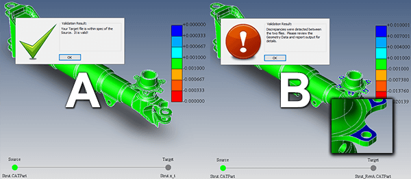
Solution: Figure 1 illustrates both contingencies; example A, illustrating a passed validation between the authority model and the derived model (tolerance set to 0.001), and B, illustrating a failed validation test. Note that in a failed case, a color ‘heat map’ is generated to highlight areas of failure (see inset graphic). In both cases, a report can be generated with a single button click, and saved to 3DPDF to clarify passed or failed validation. Reports can have custom views (orientation and zoom factor) added to the report as necessary.
8.2.1 – Acceptance Criteria & Objective Evidence
Acceptance criteria for accuracy of translated surface profile/geometry, (tolerance) must be determined by the supplier, and must ensure the end product will be within engineering tolerance/specification. Objective evidence translation validation must be retained. (Typical allowable deviation is 1/10th of the tightest engineering tolerance).
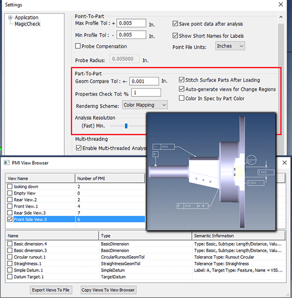
Solution: TransMagic MagicCheck allows the user to validate any two parts, independently or in the context of their assemblies, to any tolerance up to six decimal places (0.000001) in any units (inch, mm, cm). The tightest engineering tolerances can be easily located on PMI via the PMI View Browser. Figure 2 shows the MagicCheck tolerance settings dialogue, set to the default of .001 (top), as well as a screenshot of the PMI View Browser dialog box (below), with an inset showing the PMI for the selected view (Front Side View, with 6 PMI elements). Note settings for Point-to-Part and multi-threading analysis also in this figure.
8.2.2 – The Verification Process
The verification process for translation of datasets containing 3D annotation (i.e. feature control frames, dimensions, text, and/or surface geometry) must ensure that all intended entities are accounted for in the translated media.
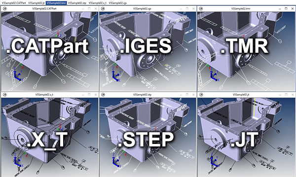
Solution: MagicCheck can read all PMI data (feature control frames, dimensions & text) as well as surface geometry. PMI data can then be translated to JT PMI or edge-based PMI in any CAD format including STEP and IGES. Figure 3 shows original CATPart PMI and resulting PMI examples for Parasolid, STEP, IGES, JT and TMR. Saving to 3DPDF will also generate graphical PMI; the important takeaway here is that you can get the PMI into the hands of whoever needs it.
Test Drive TransMagic MagicCheck
If you do not already own MagicCheck, you can test drive TransMagic SUPERVIEW, along with MagicHeal and MagicCheck Add-Ons for 7 days at no cost – just click this link to get to the free eval, or contact us a Sales@TransMagic.com or via phone at 303-460-1406.
If you have comments or questions, please contact us at social@transmagic.com.


