Validation Checking
Part validation checking is similar to revision checking, but while revision checking assumes that there was a change (and seeks to find out exactly what changed between revisions), validation checking begins with the assumption that there was no significant change between two CAD models.
Validation checking compares the authority part (provided by the customer) to the check part (usually generated as a result of translation by the supplier) to see if the geometry has changed beyond a given tolerance.
Reasons for Validation Analysis
For suppliers to perform their engineering and design tasks on the customer’s data, they often have to translate to another format, for a variety of reasons. The customer may be using CATIA, and the supplier may be using SOLIDWORKS; or, the supplier may need to convert the file to STEP so it will work with their CMM software, or analysis tool. Translating CAD geometry from one format to another usually alters the geometry to some degree because different CAD systems are built with varying precision, origin schemes, and have different ways of describing features such as complex blends. Most validation analysis falls into either of two categories:
External: Where customers require validation analysis of their suppliers
Internal: Where archival and retention processes require stored documents to be within a specified tolerance of original file dimensions.
Boeing D6-51991
Boeing is the best known example of a customer who requires validation of their suppliers. Boeing spec D6-51991 states that suppliers are required to, among other things:
- Provide flow charts of where the data moves from when it is received, documenting all CAD/CAM/CAI operations and work instructions related to the datasets.
- Demonstrate that they are able to extract MBD (Model Based Design) data and dimensional values from the original Boeing part.
- Validate the accuracy of any and all translations of original customer data; typically the allowable deviation tolerance is .0001 to .001 inch.
- Be able to identify any discrepancies between original model dimensions and translated model dimensions.
LOTAR
The other common process where validation comparison can be useful is for long-term data archival and retention (LOTAR); LOTAR is a data storage initiative that many companies take to ensure that their design data is still available years or even decades from now. A jet, for example, may be in service for decades, and as such must be serviceable via CAD information; or the existing CAD data may be needed to conceive and prove new components or designs.
By converting to a neutral CAD format such as STEP, which can be read by virtually all 3D CAD systems, LOTAR practicioners ensure that their data is readable even if they move to a new CAD system (and thus a new native format) years down the road. Before a file can be archived into a neutral CAD format, it can be validated to see that it is within a specified tolerance of the original, ensuring that the stored data is a high-fidelity copy of the native format.
How Validation Checking Works

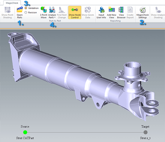
Figure 2 – Four steps to validation analysis to ensure the geometry has not changed significantly from the original dimensions.
Validation checking works similarly to revision checking, and can be narrowed down to four easy steps (see figure 2);
- Click Open Parts and select the authority part and the check part
- Set the precision of the validation (usually .0001 to .001 inch)
- There are two modes; be sure to select the Validation radio button
- Click Analyze Parts
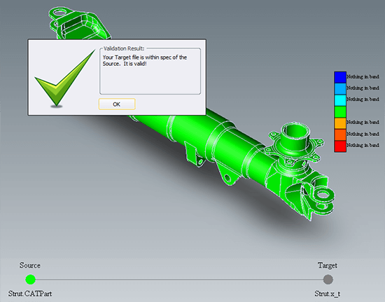
Once you click Analyze Parts, the parts will be compared and a color gradient will indicate areas that are outside of the selected tolerance. Figure 1 above depicts a validation test that was successful; both parts in this case are within .0005 of each other. To understand how the color plot works, imagine the authority part as representing an envelope that describes the geometry of the part. If there had been a discrepancy of greater than .0005, the color plot gives indications in shades of blue for geometry on the check part that exceeds the dimensions of the authority part envelope, and reddish areas indicate geometry on the check part that penetrates the envelope on the authority part.
Settings that May Apply
Some of the settings you may want to modify include gradient vs dot rendering, default view generation, and color selection for geometry that was not altered. Dot rendering is faster than gradient rendering. Default view generation creates views for top,front, right, etc., in addition to any custom views you may have added.
Validation Analysis Report

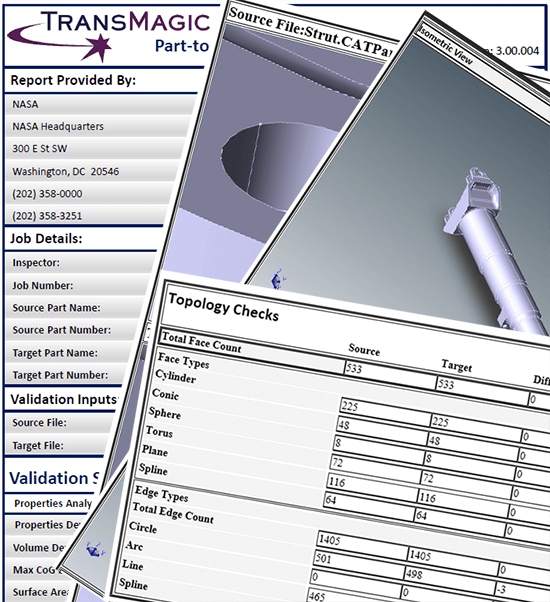
Figure 3 – TransMagic MagicCheck allows you to generate a validation analysis report with one button click.
An optional validation report certifies that the two parts are within the stated tolerance (or demonstrates where they are out of tolerance). The validation report comes with a view of both parts, generation of detail views, and includes any custom views saved by the user after analysis (see figure 3).

