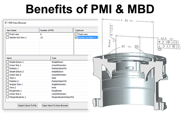
 Product and Manufacturing Information (PMI) refers to metadata such as GD&T, dimensions and notes in the context of a 3D CAD model. Model Based Definition refers to the practice of using 3D CAD models, in association with PMI to define parts and assemblies without the need for drawings. In this article we will discuss some of the benefits of PMI and MBD. In future articles we will look at specific TransMagic tools for viewing and managing PMI.
Benefits of PMI and MBD
- The ability to view metadata in the context of the part PMI allows you to clearly see GD&T, dimensions and notes in the context of the 3D model instead of in a separate drawing, making it easier to understand where the data belongs, and has the added benefit of not having to create drawings!
- Elimination of information redundancy All GD&T, dimensions and notes are in one place, eliminating the danger of engineers, designers and technicians updating data the model and failing to update the drawing, or updating the drawing but forgetting to update the 3D model.
- The ability to parse viewing planes The ability to see metadata one “layer” at a time, since PMI can be parsed out to separate viewing planes.
- The ability to view annotated sections The ability to view PMI sections (more on this below).
- Associative highlighting Depending on how the GD&T or other metadata was added to the part, you can select the highlighted data and it will highlight the geometry the data was attached to, clarifying associations to the designer or engineer. This associative feedback makes it far less likely that mistakes will be made as to what feature each value is tied to.
Downstream Advantages of PMI, MBD and automation

It’s important to remember that a simple dimensional or GD&T error can cost a company thousands or even hundreds of thousands of dollars if incorrect parts are produced. A recent study found that companies using PMI and MBD spent significantly less time on engineering documentation each week, had fewer emergencies each month, and had fewer cases of parts not properly fitting together each month.*
An example of time savings comes from one of our major automotive manufacturers which produces engine blocks containing literally hundreds of holes, with each hole requiring a sectional view with GD&T. Previous to TransMagic, the drawing for one of these blocks (with 100-plus sectional drawings) would cover a factory wall, and simply locating the right section drawing could take fifteen minutes. If one section update was missed, an entire engine block tooling setup could be flawed, leading to literally millions of dollars of scraped engine blocks downstream. Now, TransMagic makes it possible to instantly locate the sectional view, and the GD&T is always up to date, because it only exists in one place – on the model, further decreasing the risk of downstream errors.
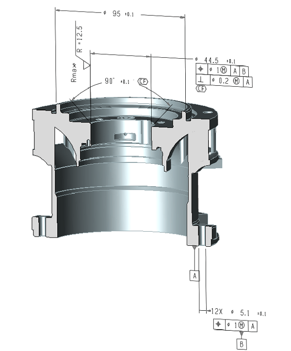
In both images in this post, you can see an aircraft engine component with sectional PMI (sectioned part courtesy of Andrey Yurasov via GrabCad). Note that the Section Cut View is current in the PMI View Browser, which makes the cut with its associated PMI visible.
Clicking on Front View would show us another set of PMI data; some parts can have dozens views, or even hundreds of views. Imagine how difficult it would be to sort through all of that data without the help of a tool like TransMagic’s PMI View Browser.
You can learn more about the PMI View Browser in the following video:
All core TransMagic products include the ability to view PMI. If you’re not already using TransMagic, you can try an eval by clicking here.
In our next PMI post we’ll discuss specific tools and settings for viewing and managing PMI with TransMagic. Until then, if you have any questions or comments, please address them to social@transmagic.com.
* To access the Lifecycle Insights study on Quantifying the Value of Model Based Definitions, click here.
