New Format Versions
- CATIA R34 Read & Write
- NX 2312 Read
- Solid Edge 2024 Read
- SOLIDWORKS 2024 Read & Write
- ACIS R34 Read & Write
- Creo 10 & 11 Read
- Inventor 2025 Read
Get the PDF: What’s New in TransMagic R14 SP2
New Features in All Products
Retain Texture on Polycam converted to JT
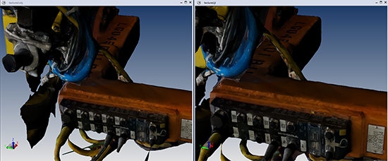 Polycam is a free tool that lets you take pictures of manufacturing environments and production facilities, and then automatically generates 3d object files with textures. These textured Obj files can be used in CAD and other visualization tools to represent existing equipment in production work areas. TransMagic R14 SP2 will let you convert the textured Obj into a textured JT file for even smaller file sizes and better CAD visualization performance. Just open the Polycam Obj file and Save As to JT.
Break All Instances
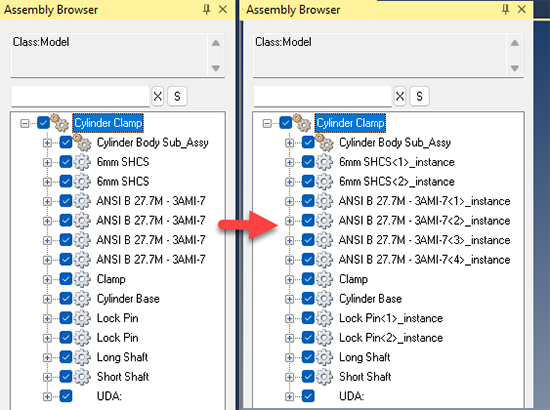 Break All Instances will break every instance in an assembly. For those who do not know, an instance is often an automatically inserted fastener, commonly seen in CAD systems. Instances are generally more effective in terms of file size than discreet parts.
However, instances can also be problematic when the user needs a unique name for each part, such as if you are saving the entire assembly to a new CAD format and the system you are bringing the data into insists that all parts have unique names.
Enhancements on General Features
Polycount Performance
Display Polycount has been drastically improved so that polygons and vertices for a medium-sized part of a few MB can be counted in about one second. (All Products)
WebGL Logo, Display, Section
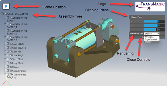 In addition to the previous capabilities to show the Model Tree, rotate, and zoom the model, TransMagic now allows you to assign a company logo to a WebGL file (which is actually a .html file), as well as giving you access to the rendering method (Shaded, Edges Shaded, or Wireframe) and the ability to invoke a Clipping Plane in X, Y and Z. (All Products)
Section Planes – Flip Direction
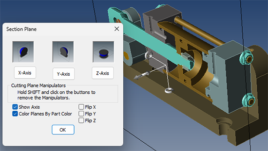 Section Planes allow you to visually cut sections through a part or assembly. Now you can Flip Direction on the section plane to see the section cut from the opposite direction.
This makes getting the section you want, in any direction, X, Y or Z, much easier. (All Products)
New Features in EXPERT Only
Standard View Orientation
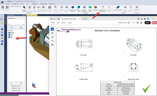 This feature requires a starting model or assembly. First, make sure the part or assembly is in a Front, Orthographic orientation (you can do this from the View toolbar).
Then click on the top part of the Standard View Orientation button, which will create four views of the part or assembly (Front, Top, Right and Isometric). You can see these views in the View Browser in the screenshot at right.
If you then would like the four views exported to a 2D PDF, click on the Standard View Orientation drop down button “Export Views to 2D PDF”. Screenshot of the Four View PDF shown at right.
Mid Sheet Body
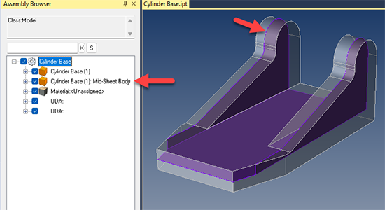 Select a part or body, and click the Mid Sheet Body button. TransMagic will attempt to generate a mid plane body for the part.
Please see example at right. Note that the Mid-Sheet Body is created as an additional body in the Assembly Browser.
Note that there are some situations where a mid plane body cannot be generated.
Replace with Bounding Cylinder
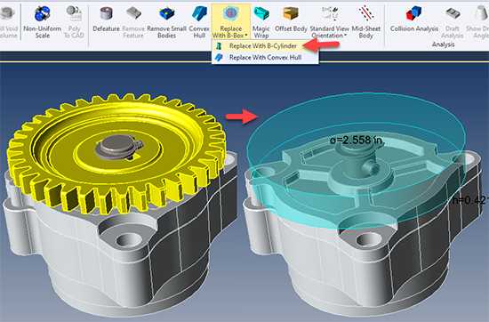 Now, just as with Replace with Bounding Box and Replace with Convex Hull, you can also replace geometry with a cylindrical bounding box.
The geometry to be replaced should be selected first, then click the option you want; your original parts will be deleted, and a bounding entity will be left in their place.
This method is useful for retaining the general area of where the parts existed, without incurring their ‘weight’ which slows down CAD manipulations and adds to file size.
The Replace options are also useful for hiding IP while retaining the general envelope of existing parts.
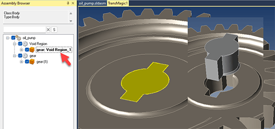
Fill Void Volume
 Fill Void Volume, as the name suggests, fills the designated voids in a model with a new solid body. This can be useful for developing core models from cavities and other mold-related work.
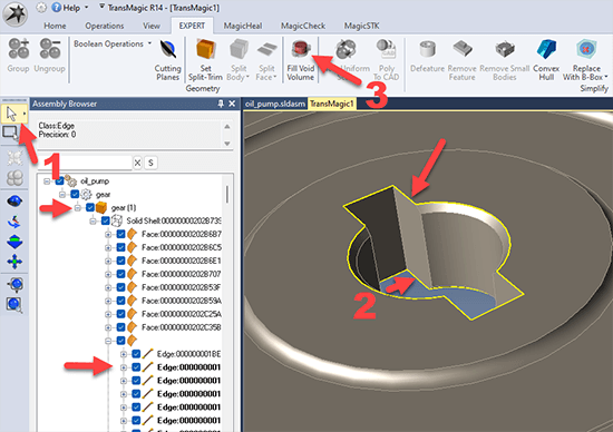
Fill Void Volume works by having you select any opening edges in a part; then, it fills any cavities up to the edges selected.
First, set Single Selection to Edges. Second, use the Single Select arrow to select each edge near where the void meets the part face.
You will need to do this wherever the void is exposed – for example, notice in the screenshot at right that the edges on the underside of the void are also selected. Third, click on Fill Void Volume.
The other arrows in the first screenshot are there to show that in the Assembly Browser, the Edges of the Gear part are selected, thus they are bolded out.
If the void does not fill, deselect your edges and try it again – a single mis-pick can cause the feature to fail.
 As you can see in the second screenshot, a solid will be created where the void was. This constitutes a new solid body in the Assembly Browser.
The resulting body can then be exported, colored, moved or scaled.
- Export is on the Icon menu – right under the TransMagic icon, click on Export Selected.
- Precise Positioning can be used to move a solid body; this can be found on the Operations toolbar.
- Scale can be used to scale a solid body, and is also on the Operations toolbar.
Enhancements on EXPERT Features
Cutting Planes – Flip Direction
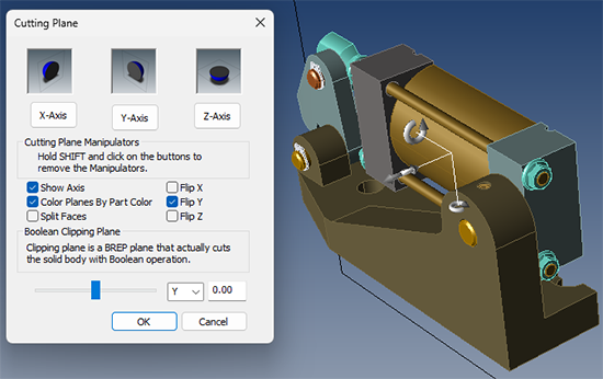 Cutting Planes are a new feature in TransMagic as of R14 SP1. They are similar to Section Planes in that they cut sections through a part or assembly, except that the result is not visual; it’s an actual Boolean cut.
Now Cutting Planes also have Flip Direction so that you can get the geometry cut the way you want it, quickly. (EXPERT Only)