This step-by-step tutorial will take you through the general View capabilities of TransMagic. The video version is immediately below, and the readable version is further down.
Open the Inventor Clamp Assembly sample file. You can find it at C:\Users\Public\Public Documents\TransMagic\Sample Files\Inventor\InvSample03\CylinderClamp.iam.
Zoom, Orbit and Pan
(See this content at 0:43 of video: https://youtu.be/Y-vqDDaIIrQ?t=43)
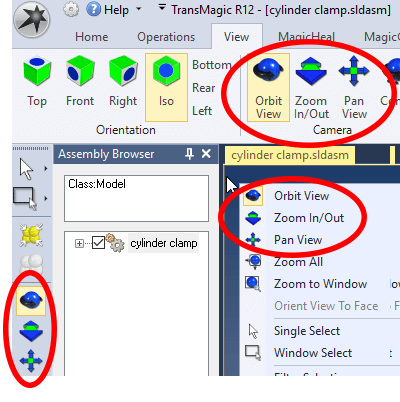
Zoom, Orbit and Pan tools can be accessed via a 3-button mouse, the View toolbar (see the left side of your screen), or the Right Mouse Button menu (right-click your mouse in the blank screen area to access this menu).
To Rotate the view of the model, press and drag your middle mouse button. To Zoom in and out, spin your mouse wheel. To Pan, you’ll have to shift modes; clicking the Pan view button in the View toolbar or the Right-Mouse Button menu will transform your left mouse button into a Pan button.
Note: For the best possible performance, not only in TransMagic but with CAD systems, consider a 3D mouse (such as the one made by 3DConnexion). 3D mice allow you to zoom, pan and rotate with one hand, leaving the other hand free for selections and screen clicks.
Zoom All, Zoom Window, Zoom Selected
(See this content at 1:13 of video: https://youtu.be/Y-vqDDaIIrQ?t=73)
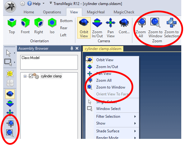
Zoom All will zoom so that all geometry is visible on the screen. This can be useful if you suspect that you have more geometry which is not appearing on the screen. Zoom Window allows you to select a rectangular viewing area using the left mouse button to press and drag, and then zooms to that area. Zoom to Selection has you select a feature, such as a face, solid body or part, which TransMagic then zooms to.
Assembly Browser
(See this content at 1:57 of video: https://youtu.be/Y-vqDDaIIrQ?t=117)
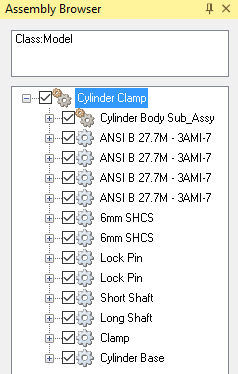
The Assembly Browser gives you a view of the data inside your part or assembly. A double-gear indicates an assembly, a single gear indicates a part, and a box indicates a solid body. Any given part can be composed of multiple solid bodies, and any given assembly can be composed of multiple parts or sub-assemblies. Assembly and part names can also be seen in this browser. Selecting a part or assembly will cause TransMagic to highlight and zoom in on that geometry on your screen.
The Assembly Browser can be hidden, docked, or thumb-tacked anywhere on the screen. You can remove the assembly browser by clicking the x, and you can find the assembly browser on your Home menu.
View Orientation
(View Orientation starts 3:27 of video: https://youtu.be/Y-vqDDaIIrQ?t=207)
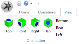
There are seven default view orientations; Top, Front, Right, Iso, Bottom, Rear and Left. Based on the way the model was created in the originating CAD system, all parts have default assigned views. You can use your orbit tool to rotate the part into the orientation you’d prefer, and then click on an orientation button adjust the default views.
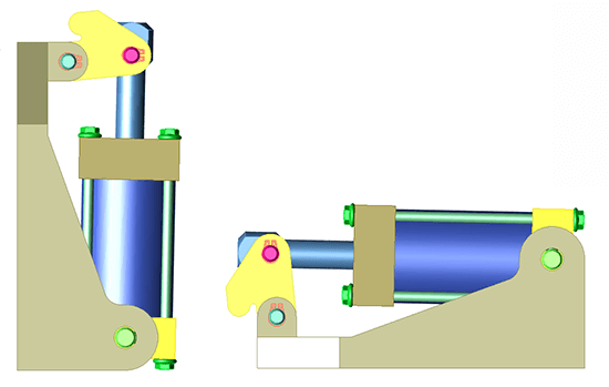
For example, if we roughly orient a part to the Top view, and click the Top view button, we get one result, whereas if we spin the view about 90 degrees and click the Top view button, we get another result (see following screenshots). for example, if we roughly orient a part to the Top view, and click the Top view button, we get one result, whereas if we spin the view about 90 degrees and click the Top view button, we get another result (see following screenshots).
Display Modes

Display modes are found on the View toolbar, in the Rendering section, and allow you to control how the model itself appears. The rendering section also contains Special Render modes for applications such as printing.
Display modes allow you to select Goraud shading, Hidden Line shading, Wireframe, Phone shading, Hidden lines shown, redraw screen, Show Faces, Show Edges, Show Vertices, Perspective, Orthographic, Show Axes and Show Shadows.
Generally speaking, you will want to work in Goraud shading, and occasionally switch to Wireframe display mode when you need to see inside geometry. Occasionally it is also necessary to turn vertices on in order to see points on the screen. Access to vertices can be useful for complex dimensioning situations.
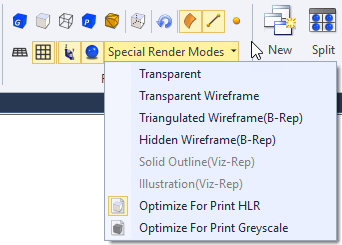
Special Render Modes include Transparent, Transparent Wireframe, Triangulated Wireframe, Hidden Wireframe, Solid Outline, Illustration, Optimize for Print HLR and Optimize for Print Greyscale. The next two images demonstrate the default shaded mode with shadows on and the default gradient background, vs the the Optimize For Print HLR Special Render Mode.
View Browser
(View Browser is starts at 5:23: https://youtu.be/Y-vqDDaIIrQ?t=323)

The View Browser is located on the View toolbar. It has its own dialog, allowing you to create and save new views which can then be regenerated by clicking that same view. To create a view, simply click Create from the View Browser dialogue.
Layer Management
Geometry can be assigned to layers and then hidden or shown, to streamline workflows. To assign geometry to a layer, select the geometry and, from the Operations toolbar, click
Keyboard Viewing Shortcuts
Arrow Keys + Shift initiates 90 degree rotates. Arrow Keys + Tab initiates smaller axial rotations. Arrow keys + Ctrl initiates pans.
