Diagnose Problems & Repair 3D Geometry – Quickly & Easily
TransMagic On-Boarding: Lesson 3 of 7
(to see all of the On-Boarding lessons, click here)
 Remember the time you had to re-model an entire assembly because the model was corrupt? Or maybe you received an IGES surface model that wasn’t watertight? That was painful and a waste of time. MagicHeal from TransMagic is the answer and is included in your 7-day FREE trial.
MagicHeal is a set of tools that help any user gain control over a broken part and bring it back into a watertight, or at least a workable CAD file. The repair features range from automatic to fine grained control. Features include:
– Auto detect and cover circuit
– Stitch a boss
– Skin between edges
– Change surface tangencies
– Force holes before covering
– Re-cover a face with a better quality surface
– Auto cover every “hole” by brute force.
One of our newer features lets you detect and correct non-manifold geometry enabling the translation between manifold (NX, SolidWorks, Solid Edge and Parasolid) and non-manifold (TransMagic, ACIS, CATIA V4/V5, Inventor, and Pro/E) CAD kernels. While repairing a file may never be “fun” — at least you’ll do it with a smile using MagicHeal.
Let’s Get Started with the Lesson (be sure to check out the video at the bottom of this page)
Start TransMagic
Click Open
TransMagic installs with many sample files. This directory is located here:
“C:\Users\Public\Documents\TransMagic\Sample Files
 Load the file …”Sample Files\MagicCheck\plastic_enclosure_missing_surfaces.igs”
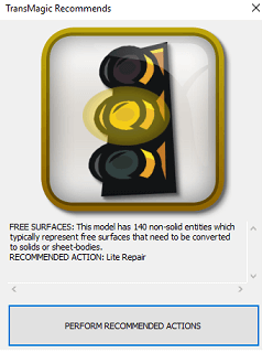
TransMagic will open the part and automatically report that there are many free surfaces and recommends Lite Repair.
If TransMagic does not automatically try to repair the part, you can initiate the Auto Repair Wizard by clicking on Auto Repair Wizard (in the middle of the Home toolbar).
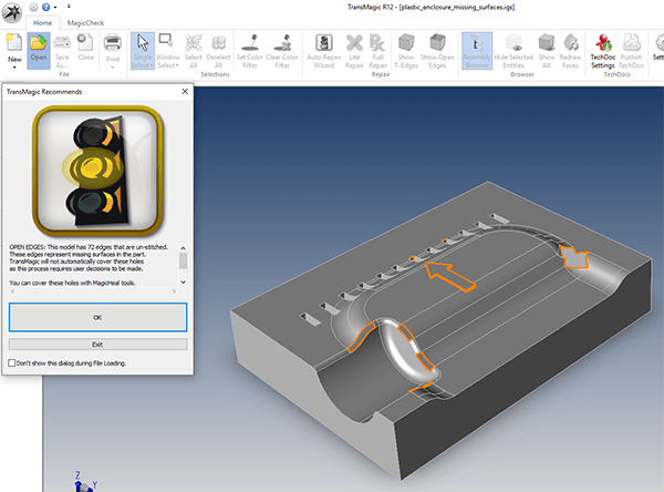
TransMagic finds 72 unstitched edges and recommends you use MagicHeal tools to complete the repairs (see image at right).
Click OK to dismiss the Auto Repair Wizard, and zoom in on the arrow boss on the top of the plastic enclosure. This arrow boss is missing its sidewalls, so we will select the top and bottom edge of the arrow in order to build new ones.
 Next, to replace the missing walls on the ‘arrow’ feature on the top of the part, first click the Single Select arrow (at the top of the left toolbar) so that you have the ability to select edges.
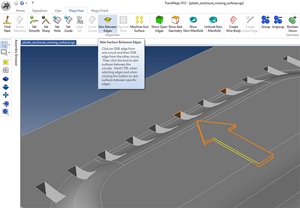
Then select the lower and upper circuit edges as shown (in yellow) in the screen capture below, by holding down the Ctrl key and clicking with your left mouse button. Then, from the MagicHeal toolbar, select Skin Between Edges.
This will generate a sidewall surface between both of the selected surfaces. Skin Between Edges is similar to what some people may know as a ‘ruled surface’. This solution can be used wherever you have two good edges to select, whether they are closed circuits as in this case, or unclosed edges.
![]() The arrow boss now has sidewall surfaces all the way around. You will notice that the new surface is purple; this is to distinguish it from the original part surfaces. It’s important to note that generated surfaces are only as good as the edges they are built upon. More about this later.
The arrow boss now has sidewall surfaces all the way around. You will notice that the new surface is purple; this is to distinguish it from the original part surfaces. It’s important to note that generated surfaces are only as good as the edges they are built upon. More about this later.
 Click the Find Next button on the left side of the MagicHeal toolbar to find any remaining open circuits. TransMagic should automatically zoom in to the next open circuit.
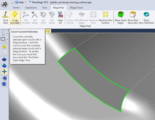
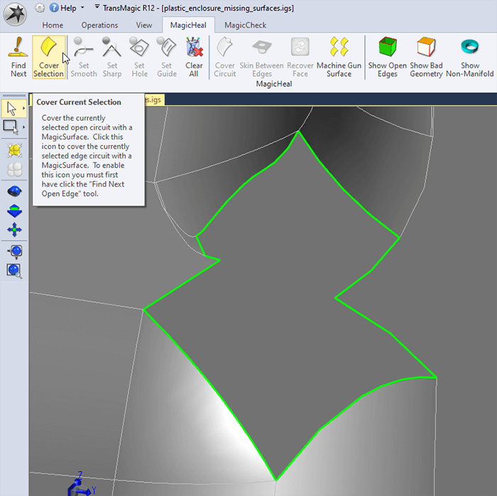
In the figure at right, you can see that Cover Selection is about to be clicked, which will cover the open circuit.
However, before you click Cover Selection, assign the optimal attributes to the edges. In this case, one of the edges was selected and Set Smooth was applied. You can tell that Set Smooth was applied because the edge is now green.
When selecting edges, you can use the Single Select tool which is just under the Find Next button.
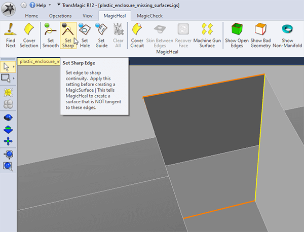 This open circuit should have sharp edges, since it is not blending with any neighboring surfaces. In the figure, you can see that the Single Select arrow is active on the left side of the screen, and one edge in the open circuit has been selected (selected geometry is yellow, by default). Once the geometry is selected, click Set Sharp, then you can click Cover Selection.
 This open circuit can also be covered using Set Smooth, however in this instance it’s important to note that we are covering an opening that was originally at least two surfaces.
MagicHeal can cover this opening, but with two faces missing, and being replaced with a single face, there is the possibility that the new geometry will not be exactly the same as the original geometry.
As mentioned earlier, that’s why MagicHeal creates new surfaces that are purple, to clarify which surfaces are new, in case you need to perform downstream checks to make sure the newly repaired part will work.
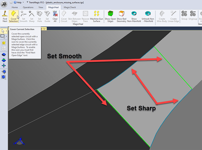 In this situation, two of the open circuit edges need to be set to smooth, and two need to be set to sharp. To do this, make sure you the Single Select arrow is active, and use the CTRL key to select the two edges shown as green in the screenshot, and keep the CTRL key held down while you click on ‘Set Smooth’. Now select the other two edges with CTRL held down and click on ‘Set Sharp’. You’ll notice that each attribute has its own color. Then go ahead and Cover Selection.
 Once you’ve repaired all the holes in your model, the new geometry needs to be stitched into place. That’s simply a matter of selecting all the geometry and running Lite Repair. Here’s how to do it.
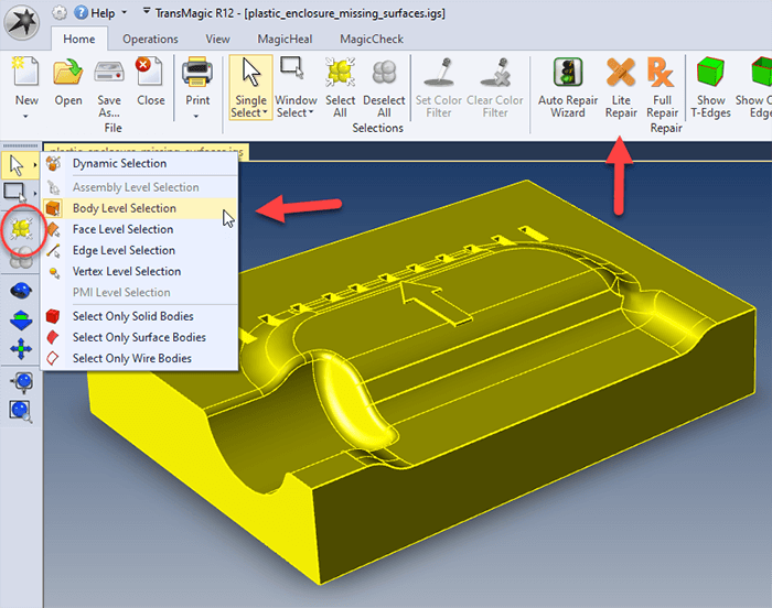
Start by selecting all the geometry, either by selecting Select All from the left toolbar, or by using Single Select > Body from the left toolbar. Then click Lite Repair from the Home toolbar.
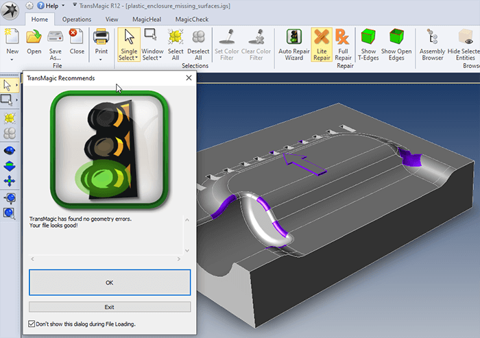 Once Lite Repair runs, you should get the ‘green light’ indicating that your geometry is good!
If you want to change the colors of your part, or check mass properties to makes sure that this file is watertight, see the video below.
The video below covers the basic steps shown in the tutorial, as well as how to change part color and check watertightness by running a mass properties calculation.
End of Lesson 3
Thanks for taking the time to review this lesson. If you have questions, please email us at support@transmagic.com or reach out to us via chat from transmagic.com.
This is lesson 3 of 6 of the introductory on-boarding series for TransMagic. Visit TransMagic On-Boarding for a list of all the lessons.
Please feel free to share this lesson with others in your company. They can get their own trial by visiting this page TransMagic.com/get-a-trial.