by Brad Strong | Aug 24, 2017 | Blog, CAD Translation, Polygonal Output, What's New |
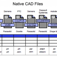
Being able to read and write a multitude of CAD and polygonal formats increases your flexibility as a company, and widens the range of companies you can deal with. TransMagic allows you to read and write native CAD formats (such as CATIA), geometric modeling kernel formats (such as Parasolid), neutral CAD formats (such as STEP), and polygonal formats (such as STL). Within each of those formats, TransMagic also gives you access to a wide range of versions. Here’s a summary of TransMagic’s supported formats: Native CAD Formats TransMagic can READ AutoCAD (.dwg, .dxf) CATIA (.model, .catpart, .catproduct) Creo (.prt, .asm) Inventor (.ipt, .iam)...
by Brad Strong | Apr 10, 2017 | Blog, CAD Translation, CAD Viewing, Polygonal Output, What's New |
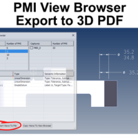
Exporting PMI to 3D PDF Exporting PMI to 3D PDF is a simple matter of choosing the PMI views you want to export, and clicking the Export Views To File button. The ability to export CAD views, along with associated PMI, makes communicating with internal and external team members who may not have a CAD system, or even a CAD viewer. 3D PDF is a great equalizer since the free Acrobat PDF reader is already installed on the vast majority of computers. In the first figure, there is one view selected in the PMI View Browser (MBD_02). This view is the ‘front’ view, containing three GD&T elements. Only the PMI for the selected view is visible, allowing...
by Brad Strong | Mar 20, 2017 | 3D Printing, Blog, CAD Translation, CAD Viewing, Polygonal Output, Support, What's New |
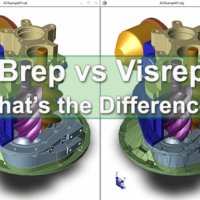
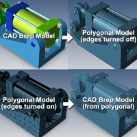
What are the advantages of Brep vs Visrep models, and how do you tell them apart? Brep Models Brep refers to Boundary Representation. As the name suggests, the boundary between solid and non-solid geometry is in view here, the solid geometry being a collection of interconnected surfaces. This is a mathematically precise representation of geometry. Depending on the format and the CAD software you have in your possession, the features and underlying sketches may be editable, or the shapes may be editable – but generally speaking, if you don’t have the CAD system used to create the file, you cannot edit the features or sketches unless you run a...
by Brad Strong | Feb 27, 2017 | 3D Printing, Blog, CAD Performance, CAD Translation, Polygonal Output, What's New |
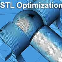
30 Years of STL From a humble beginning in 1987, when STL was developed by the Albert Consulting Group for 3D Systems, the format has been become a mainstay for 3D printing and has remained virtually unchanged over all these years. The name STL was derived from STereoLithography; STL uses a series of linked triangles to roughly define the surface geometry of a 3D CAD model. General STL Optimization Guidelines Whether you’re using the STL file for 3D printing, machining, or other purposes, you’ll want to set the resolution or mesh density to meet your product or prototype requirements. If your resolution is too rough, you’ll end up losing or...
by Brad Strong | Feb 13, 2017 | 3D Printing, Blog, CAD Translation, Polygonal Output, What's New |
Pre-processing for polygon reduction is possible using polygon facet resolution settings. Since the Polygon Reduction tool starts with a default facet density, it can sometimes be useful to adjust that pre-set facet density to a higher value. More information about the Polygon Reduction tool can be found here. Change Facet Resolution Starting with a sample CAD component, you can select the model with the Single Select tool, or just “Select All”, and right click to get the Change Facet Resolution options (see figure 1): Normal: The lowest resolution option, approximately 27 segments on a cylinder or hole. Medium High: Slightly higher than normal,...
by Brad Strong | Dec 15, 2016 | 3D Printing, Blog, CAD Translation, Polygonal Output |
One question we get regularly at TransMagic is “Can I convert polygonal models to CAD models?”. Well now the answer is yes; as of release 12, TransMagic Expert has the capability to convert polygonal formats to geometric CAD formats. I asked TransMagic’s head of development, Craig Dennis, about this process, as well as some of the benefits and challenges of the Poly to CAD process: Polygonal formats are comprised of triangular polygons vs. the true geometry in CAD files such as spheres, planes, torus, cones, free form surfaces (NURBs), etc. The conversion from true CAD geometry to triangles is very easy (CAD to *.stl); however, the inverse,...